Basic building instructions for a concentrated solar water heater are available by clicking here.
Construction of such a system is well within the capabilities of even the most limited DIY enthusiast and only a few common tools are required. If the pump used to move anti-freeze/oil around the system is a 12V solar powered device, there is no need for the assistance (and expense) of a professional electrician. The plumbing skills required are limited to joining copper pipes together which is not very taxing – particularly if compression joints are used rather than soldering.
The most complicated part of the whole system to construct is the reflective parabolic trough. Time and money spent here is well invested since even the smallest increase in efficiency will result in reduced water heating bills.
Making a Prototype Parabolic Trough
Before embarking on building a full-sized parabolic trough it is well worth making a scaled down model from mirrored cardboard. This is available for around 30p per sheet, so any mistakes you make at this time will provide you with a cheap lesson. Thick cardboard (from old boxes) can be uses to construct the rest of the prototype trough.
Choose a Parabola

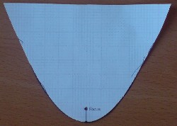
Pictured above is the parabolic curve used in our prototype parabolic trough. This was printed out directly onto paper and a piece of the mirrored card cut so that its width was equal to the length of the parabolic line printed. To make end supports, the parabolic curve was cut out to make a template which could then be used to cut out two identical cardboard shapes in its form.
The mirrored card was then stapled to the cardboard end supports in multiple locations to ensure that it took the exact shape of our chosen parabola.
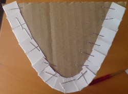
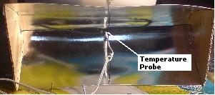
This threw up the first problem which can occur with such parabolic troughs. While the reflective surface closely matches the parabola near the ends of the trough, in the centre of the trough it opens out.

As the photograph above shows – the trough has become wider at the centre than at its ends indicating that the trough is not correctly shaped along its length. This is a common problem when thin materials are used to make the trough – mirrored card is of course far thinner than anything you would use in a full-sized trough, however the problem can still occur to a lesser degree with all materials.
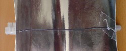
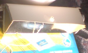
One solution is to construct a wooden framework under the trough so that the reflective surface can be held in the correct shape along its whole length. However it is much cheaper to use lengths of suitably strong wire to hold everything in shape. This is what we have done in this prototype as pictured below.
Testing the Parabolic Trough
Testing the trough accurately under the British sunlight is a bit difficult because of passing cloud cover. Therefore testing took place under controlled conditions using a 150W halogen lamp in place of the sun. Using a standard thermometer or probe was not possible because of the shadows such a device would cast on the trough, therefore the Power Analyzer PRO miniature temperature probe was used.
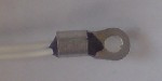
Instead of using a pipe full of fluid to as the heat collector a piece of wire was threaded through the two pipe holes and pulled taut with the temperature probe threaded on. This positioned the temperature probe just one or two millimetres above the focal point of the parabolic reflector – good enough for some basic testing.
Temperature Measurements in the Parabolic Trough
First of all the temperature probe was positioned 30cm away from the halogen bulb and left for 10 minutes. A maximum temperature of 26.0 degrees Celcius was recorded.
Then the thermometer probe was positioned in the parabolic trough as described above and left for 10 minutes. The maximum temperature recorded jumped up to 31.4 degrees Celcius.
Since the temperature probe is made of shiny metal, we wrapped it in black insulation tape to recreated the effects of painting the copper pipe black. Outside the trough the temperature recorded went up from 26 degrees to 28.2 degrees Celcius. When we put the black temperature probe into the trough again for 10 minutes the new maximum temperature recorded was 33.3 degrees Celcius.
Moving the probe closer to the bulb, at 20cm distance we measured 29.5 degrees Celcius outside the trough, and 37.9 degrees Celcius in the trough, and at 10cm distance we measured 32.8 degrees Celcius outside the trough and a massive 46.3 degrees Celcius in our tiny 26 x 12cm trough.
Having proved that the parabolic trough prototype is doing what it is supposed to, it is a simple task to scale up the trough and build the finished concentrated solar water heater system.