REUK.CO.UK
The Renewable Energy Website
This is the printer friendly version of the Repeat Timer Circuit article from the Renewable Energy Website REUK.co.uk.
Click here to print
Printed at 12:53pm 13th June 2026
Repeat Timer Circuit
Make a repeat timer circuit with large intervals between ON times
In our article Timer Circuits with 4060B (1) we looked at how the 4060B binary counter can be used to make a timer. Such a timer can be used to time intervals lasting from seconds to 24+ hours, but when used as a repeat timer (i.e. toggling between ON and OFF indefinitely) the ON time is equal to the OFF time - for example, 10 minutes ON, 10 minutes OFF, 10 minutes ON etc.
It is more common for a timer to be required to have different ON and OFF times - for example, 1 hour OFF, 1 minute ON, 1 hour OFF, 1 minute ON, etc. For time intervals of up to 5-10 minutes, a 555 Timer (2) chip can achieve this with the different ON/OFF times set using a resistors (3) and capacitors (4). However, for longer time intervals, the 555 is not reliable.
Using a 4060B with a 555 Timer
One of the easiest ways of putting together a reliable timer with long OFF intervals and short ON intervals is to use a 4060B together with a 555 timer. The 4060B accurately times the long OFF interval (up to 24 hours), and the 555 the short ON interval (up to 5 minutes).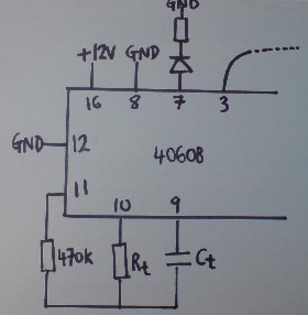
Pictured above is the 4060B part of the circuit which determines the duration of the OFF time interval. The values of the capacitor Ct and the resistor Rt fix the frequency (and therefore the speed) of the timer according to the formula:
Frequency = 1 / (2.3 x Rt x Ct)
Increasing the values of Rt or Ct* will slow down the timer; reducing them will speed up the timer. * Ct should be a non-polarised capacitor.
The LED connected to pin 7 of the chip is used to estimate the freqency of the output from pin 3. If the LED goes through one complete ON/OFF cycle every 2 seconds (flashing ON for 1 second then OFF for 1 second etc), then it will take 1,024 times those 2 seconds for the output of pin 3 to go though one complete cycle = 2,048 seconds (34 minutes).
In our experimentation we found that a 10uF non-polarised capactor and a 6K8 resistor gave us a 40 minute pin 3 cycle time - i.e. ON for around 20 minutes, OFF for around 20 minutes and so on.
The 555 timer part of the circuit (pictured below) is used to time the short ON interval.
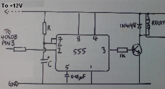
In this configuration, the output from pin 3 of the 555 chip is high (therefore energising the relay (5)) when power is applied to the circuit from pin 3 of the 4060B. The relay will remain energised for a time period* set with the resistor R and capacitor C before turning off and staying off.
* In our experimentation we used R=470K and C=100uF to obtain a 1 minute timer.
How Does this Timer Circuit Work
Let's say we need a timer which will cycle OFF for 59 minutes and then ON for 1 minute indefinitely perhaps for an hourly monitoring application. First of all we set up the 4060B so that the time taken for the LED at pin 7 to go through one complete ON/OFF cycle is 1/1024 of 60 minutes = 3.52 seconds. (It is best to measure the time taken for 20+ cycles and then use a calculator to work out the time for one cycle accurately). Set up the 555 timer circuit for one minute changing the value of the resistor (using a variable resistor (6) makes this easier).When the output of pin 3 of the 4060B goes high, the 555 circuit receives power. The relay will be energised as long as pin 3 of the 555 chip is high - a time we set as one minute in this example. After that one minute pin 3 of the 555 will go low and stay low. The 555 circuit will continue to receive power from the 4060B for 60/2 minutes = 30 minutes, but the relay will stay de-energised after the first minute. Then, after 30 minutes, pin 3 of the 4060B will go low again for 30 minutes removing power from the 555 circuit altogether which resets it. The cycle then repeats itself.
In short, the relay will be energised for one minute every time pin 3 of the 4060B goes high - an event which happens once every 60 minutes.
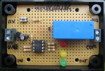
Bespoke Timer Circuits
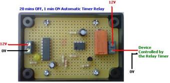
Pictured above is a 20 minute OFF, 1 minute ON timer we put together for a customer using the 4060B and 555 ICs. If you require any type of bespoke timer relay circuit for any application, please contact neil@reuk.co.uk (7) with details of your exact requirements.
Unless specifically requested, all of our timers are now based on microcontrollers rather than the 4060B and 555 chips - see the end of the article Timer Circuits with 4060B (8) for the reasoning behind this, or here: Make a PICAXE Repeating Timer (9) for our automatic microcontroller (PICAXE (10)) timer code generator so you can make you own repeating timer and learn to programme and use microcontrollers at the same time.
If you would like a repeating relay timer with user-settable ON and OFF durations, have a look at our REUK Super Timer (11) and REUK Super Timer 2 (12). These have independent ON and OFF durations from 1 second to 99 hours which can be set by the user with a button.
Web Link References
(1) http://www.reuk.co.uk/Timer-Circuits-With-4060B.htm(2) http://www.reuk.co.uk/searcher.php?search=ne555
(3) http://www.reuk.co.uk/Resistor-Colour-Codes.htm
(4) http://www.reuk.co.uk/Smoothing-Capacitors.htm
(5) http://www.reuk.co.uk/Relays-and-Renewable-Energy.htm
(6) http://www.reuk.co.uk/buy-VARIABLE-RESISTORS.htm
(7) Email address: neil@reuk.co.uk
(8) http://www.reuk.co.uk/Timer-Circuits-With-4060B.htm
(9) http://www.reuk.co.uk/Make-a-PICAXE-Repeating-Timer.htm
(10) http://www.reuk.co.uk/PICAXE-Microcontrollers.htm
(11) http://www.reuk.co.uk/buy-REUK-SUPER-TIMER.htm
(12) http://www.reuk.co.uk/buy-REUK-SUPER-TIMER-2.htm
Article from REUK.co.uk:
http://www.reuk.co.uk/Repeat-Timer-Circuit.htm
Published: 24th September 2014
© REUK 2026