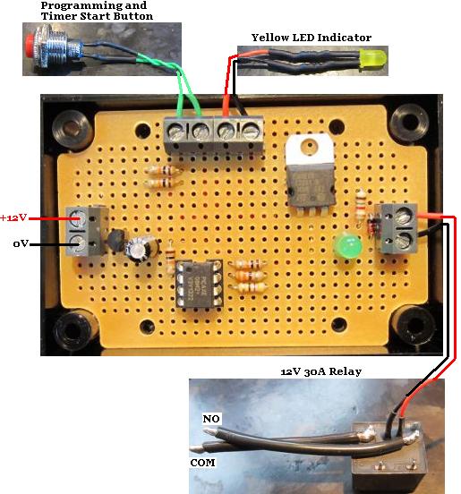
In a recent post we showed our 24V Low Voltage Disconnect with Data Display. This device monitors and logs the voltage of a 24V battery bank, disconnects the output loads if that voltage is too low to protect the batteries, and has an LCD display on which the last 100 days of battery voltages can be checked, summarised, and the maximum and minimum recorded voltages displayed for analysis.
This device is built around a PICAXE microcontroller. These are simple to use and quick to programme microcontrollers, but they have a few ‘features’ which can make life difficult (sometimes making an Arduino a far better alternative). PICAXE chips can only process numbers in the range 0-65535, they cannot process negative numbers, and cannot process floating point (decimal) numbers.
In most cases those limitations are not an issue, but with our 24V LVD for example it was. The microcontroller is powered via a 5V regulator. In order to measure incoming voltages over 5V, a voltage divider (Wikipedia) is required – a pair of resistors connected in series with one end connected to the incoming voltage to be measured and the other end to 0V. The values of the resistors are chosen so that the voltage measured where the two resistors meet is in the range 0-5V across the full range of likely input voltages.
For our standard 12V low voltage disconnects we use a 47K resistor for R1 and a 10K for R2. The voltage output from this voltage divider is equal to R2/(R1+R2) multiplied by in the input voltage. So, if the input voltage is 13.00V for example, the voltage divider output voltage will be 13*(10K/(10K+47K))=2.281V which the 10-bit ADC on the PICAXE will see as (2.281V/5V)*1023=467. Only when the input voltage exceeds 28.5V will the voltage from this voltage divider exceed 5V, and 28.5V is never going to be seen from a 12V battery.
With our 24V datalogging LVD we chose 68K for R1 and 10K for R2. This gave an input voltage range of 0-39V corresponding to the ADC range of 0-1023 which is perfect for a 24V battery system. However, we hit upon a problem.
We work out what an input voltage of 1V corresponds to as an ADC value after passing through the voltage divider. With the 68K/10K divider on our 24V LVD, 1V on the input corresponds to an output of 0.12821V which corresponds to (0.12821/5)*1023=26.23. Therefore, if we divide the ADC value on the microcontroller by 26.23, we calculate the input voltage.
BUT, the PICAXE chip can only do integer arithmetic. An ADC value of 415 in this example corresponds to a measured input voltage of 415/26.23=15.8216V, but with integer arithmetic 417/26=15V so off by almost a full Volt.
In order to retain resolution and accuracy while forced to use integer arithmetic, we multiply the ADC reading by 100 and divide it by ten times the per volt ADC value. The result given is ten times the input voltage – for example (415*100)/262=158 which means 15.8V which is close enough to the actual value.
But, this approach can then lead to another problem. In the case of our 24V LVD with the 68K/10K voltage divider, when the input voltage exceeds just below 25V (which will almost always be the case with a maintained 24V battery bank), the ADC value is greater than 656. When we multiply this ADC value by 100 we get a number of over 65600 which the PICAXE (with its maximum number limit of 65535) cannot process. For example it will see 65536 as 0, 65537 as 1, 65538 as 2, and so on and will think that an input voltage of 25V is less than 1V which is not much use.
There are many (very complicated) ways around this maximum number problem using variables and/or the EEPROM to store parts of large numbers while doing calculations, but in the case of the 24V LVD with datalogger, all the internal data EEPROM was dedicated to datalogging, and all the variables were already being used. Therefore, instead of multiplying the ADC value by 100 and dividing it by ten times the per Volt ADC value, we modified our code to multiply the ADC value by 50 and divide it by five times the per Volt ADC value. This results in a small loss of accuracy of less than 0.1V at the upper range of predicted voltages, but works well enough for this particular device.
So, when choosing a voltage divider for an accurate voltage measuring device with a PICAXE chip, choose the resistors to ensure that the full possible input voltage range is more than covered, and also that any multiplication of ADC values in order to maintain resolution with integer arithmetic does not generate numbers over 65535. (Alternatively just use an Arduino with floating point arithmetic!)
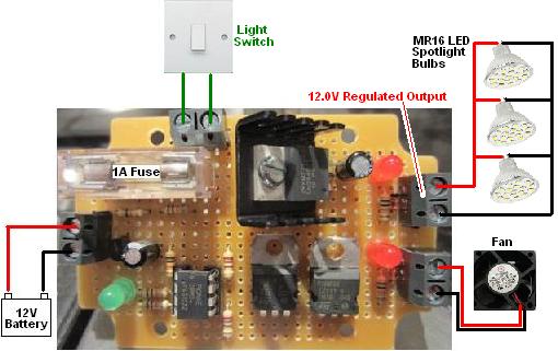
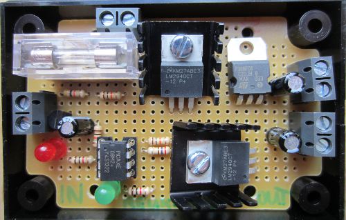
 This controller is based around our low voltage disconnect products. It constantly monitors the voltage of the battery bank. When the voltage falls below a user set low voltage (e.g. 12.0V), the on board relay closes which connects a mains powered battery charger to the battery bank.
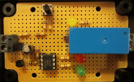