East West Solar Water Heating Pump Controller

We have recently finished work on a new solar water heating pump controller to be used where the array of solar water heating panels is split between an East and a West facing roof instead of the more typical single South-facing (in the Northern Hemisphere) solar array. This controller has been based around our 2014 Solar Water Heating Pump Controller with Display with some additions and changes.

Solar water heating pump controller for use with an East / West solar array
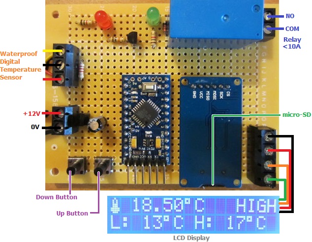
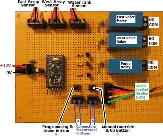
This controller has connections for three waterproof digital temperature sensors – one for the East array, one for the West array, and one for the hot water tank (or pool).

The customer for this controller did not want to have the water flowing through both solar arrays at the same time to prevent heat collected on the hotter sunny side of the roof from being immediately radiated away from the cooler side. Therefore his system features two solenoid water valves which, when the pump is turned on, will ensure that water only flows through the hotter of the two solar heating arrays.

Display for East / West solar water heating pump controller

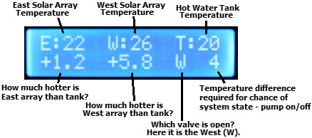
The display (LCD) for this controller shows the three measured temperatures on the top line, the temperature difference between each solar array and the hot water tank (or pool), which if either of the valves is open (therefore also indicating that the pump is running), and the temperature difference (diffON or diffOFF) required for the system to change state (i.e. for the pump to turn on or off).

In the above photograph, the valve on the West side is open, and the west solar array is +5.8 degrees Celcius hotter than the hot water tank. When this temperature difference falls below 4 degrees (diffOFF), as the East array is relatively cool (just +1.2 degees hotter than the tank) the West valve will close, the pump will turn off, and the display will now show diffON – the temperature difference required before the pump can be turned on again. (If the East array had been hotter than the tank by more than diffON at this time then the pump would keep going, the East valve would open and the West valve would close).

This controller also has a manual override facility which lets the user force the pump to run with the East valve open, the West valve open, or even both valves open at the same time – for example while testing. The values of diffON and diffOFF can be set by the user as per the standard 2014 solar water heating pump controller.

If you need a controller like this (or any other solar water heating pump controller), please email neil@reuk.co.uk with details of your exact requirements.

Vineyard Frost Detection Warning Indicators

Pictured below is a frost detection warning light system we have been putting together to be used in vineyards (though it could of course be used for any other temperature sensitive crops).

Frost detection warning circuit for vineyardsThis device takes a 12VDC power input, and connects to a waterproof DS18B20 digital temperature sensor. On the output side are three 12V outputs which will be connected to three 2.4W LED lighting units (one red, one yellow, and one green) and mounted on towers attached to the vineyard posts so that they can be seen from up to 100 metres away. (In the photo above we are just using three individual LED bulbs of the relevant colours during testing and calibration.)

When the temperature is measured to be >+1 degree Celcius, the green light is on. When the temperature is from 0 to +1, the yellow light is on. When the temperature is between -1 and 0 the red light is on. When the temperature falls below -1 degree Celcius, the red light flashes.

testing and calibrating a frost warning system

Above you can see testing in progress. The bowl on the left contain water, salt, and ice (measured to be -5 degrees Celcius after half an hour in the freezer) and the bowl on the right just ice and water (measured to be just above 0 degrees Celcius). The red LED is in the middle of flashing to indicate that the measured temperature is below -1 degree Celcius.

We have made multiple identical units for this particular vineyard which will be distributed around the area making it possible for the vintner to know immediately where any pockets of frost are located.

If you need any kind of thermostat, low/high temperature warning system, or temperature datalogger, email neil@reuk.co.uk with details of your exact requirements.

Thermostat with Datalogger and LCD Display

Pictured below is a thermostat we have just completed which includes an LCD display and temperature datalogging to a micro-SD card.

Cooling thermostat with LCD display and SC card dataloggerThis will be used to control and monitor a small (4′ x 4′ x 6′) shed cooling system. The cooling parts of a second hand fridge have been mounted to an inside wall of the shed, and this thermostat with its digital temperature sensor and relay is used to turn the cooler on and off as and when required to keep the shed cool.

The display shows the current temperature of the shed and the system status. The user can set the high temperature and low temperature thresholds at which the cooler will be turned on and off respectively; and their chosen thresholds are displayed on the bottom line of the display.

Every 30 seconds the temperature of the sensor and the cooler status (on=1, off=0) are logged (written to a csv text file on a micro-SD card) for later analysis on a computer using Excel or similar.

If you need something similar to this, or anything else utilising temperature datalogging, monitoring, and control, email neil@reuk.co.uk with details of your requirements.

Dawn Dusk Lighting Controller with Regulated Output

Pictured below is a modification of our standard Mini REUK Dawn/Dusk Lighting Controller which has the addition of a regulator on the output so that it can be connected directly to LED lighting, and connections to enable a PV solar panel to be connected to the battery via the board.

REUK Dawn Dusk Lighting Controller with Regulated 12V OutputWe used an LM2940CT-12 regulator on the output side which will supply up to 10 Watts of 12.0V output to protect sensitive LED lighting from excessive voltage from the solar charged battery. (If the battery voltage falls below around 12.3V, the output voltage will fall to around 0.3-0.5V below the battery voltage).

We added a Schottky Diode to solar panel input so that the battery will not drain charge through the solar panel at night. A Schottky type diode was chosen as only around 0.3V of solar voltage is dropped through it compared to the 0.6V+ typically dropped through a standard silicon type diode.

Header Tank Filling Pump Controller

Pictured below is a controller we have just finished for a customer. We make a lot of rainwater toilet flush pump controllers, but this one is a little different from the norm.

Automatic header tank filling pump controller with time delay and use programmingThis controller is for a pump with its own integrated run-dry float switch protection. A second float switch is located in the header tank. When the header tank float switch goes low (as the water level drops), a user programmable (1 to 99 minutes) timer starts a countdown. When the timer has elapsed, the pump is switched on with the on board relay, and is run until the float switch goes high on the increasing water level.

This version will work well for situations in which water is taken regularly from the header tank, and in particular in situations in which water will be taken from the header tank a few times typically during the timer countdown after the water level first used – e.g. multiple people coming home at the same time and all using the toilet.

The advantage of this system is that only one float switch is needed in the header tank (and there is no need to estimate the time taken to fill the tank by the pump etc).

The disadvantage of this system is that sometimes when the header tank is not being used, the water level will drop because of evaporative losses or leaks in the pipework etc. To mitigate against this, we set up the controller to run the pump for a minimum of 30 seconds each time it is turned on, and also to require one continuous second of changed float switch condition before any action is taken so that turbulence is ignored and to avoid multi-switching (which could rapidly damage the pump).

If you need a pump controller for your well, sump, rainwater toilet flushing, etc, then please email neil@reuk.co.uk with details of your exact requirements.