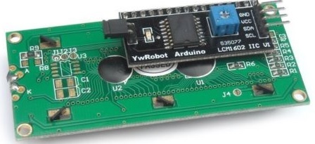
At REUK we use a lot of 16×2 LCD display modules of the type pictured above (and available here: 16×2 LCD Arduino Module from just £3) for some of the products we sell in the REUK Shop and more often in our bespoke products.
These units have a standard Hitachi HD44780 compatible 16 x 2 character liquid crystal display (LCD) to which is pre-soldered a small controller board (in the pictured example from YwRobot) enabling [i2c] communication between the LCD and an Arduino or Raspberry Pi over just two wires (plus two more wires for the power inputs). In the case of the Arduino, pin A4 connects to SDA on the module and pin A5 to SCL. Many Arduino libraries (e.g. LiquidCrystal_I2C) are available which have typically made these LCDs very simple to set up and use even for beginners.
In all of the example code for these libraries, the default address on the i2c bus for these LCDs is always given as 0x27, and so after years of using them, and it always being correct, it just became automatic to expect it to be true.
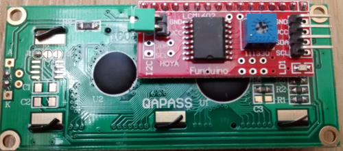
However recently (since April 2015) the small modules on the backs of the available displays have suddenly changed from being red (Funduino – pictured above) to being black (YwRobot) – probably because the YwRobot modules are cheaper than the Funduino units.
In general, the YwRobot modules work identically to the old Funduino units with one key difference. We have found that approximately one unit in five (including from different suppliers) is not preset with 0x27 as its address meaning that we have had to modify our long established, tried and tested Arduino code to get them to work.
In the most part we have (after some research) found that the address 0x3F works with these units, but we have also had a few units for which neither 0x27 nor 0x3F works. In those cases we have to use the i2c scanner sketch to find out what the address is for each particular display which is a pain. The main problem is that almost none of these units are supplied with any accompanying documentation, and those that do always state 0x27.
If you have had similar problems, please email neil@reuk.co.uk with details of the address you have discovered for the display(s) you purchased and the source of the display(s) so that we can build up a comprehensive reference document to help people who have purchased a display and have no idea of its address. The consistent 0x27 addressed Funduino units are getting harder to source and don’t seem to be coming out of China any more.
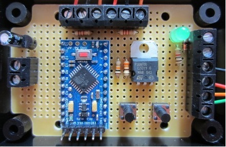
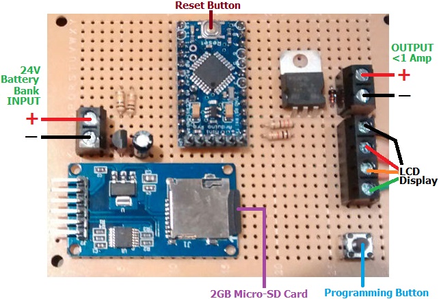 This particular unit is destined to be used by a company specialising in the maintenance of the UK’s transport infrastructure; with the low voltage disconnect used to protect batteries from being overly depleted, and the datalogger used to track the rise and fall of battery voltage over time.