We recently built and tested a very simple SD card datalogger based around an Arduino Pro Mini – the smallest and cheapest Arduino board commonly commercially available. We have previously described datalogging to an SD card with an Arduino in our blog post Arduino SD Card Datalogging (to log temperatures). In this example we are instead logging the voltage of a solar charged battery used to power the lights in a shed.
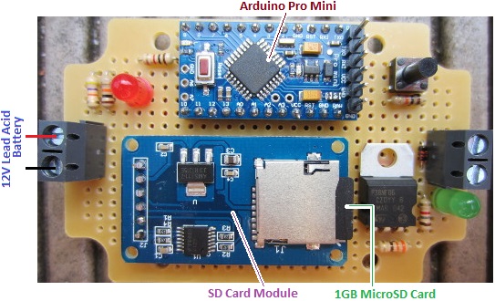
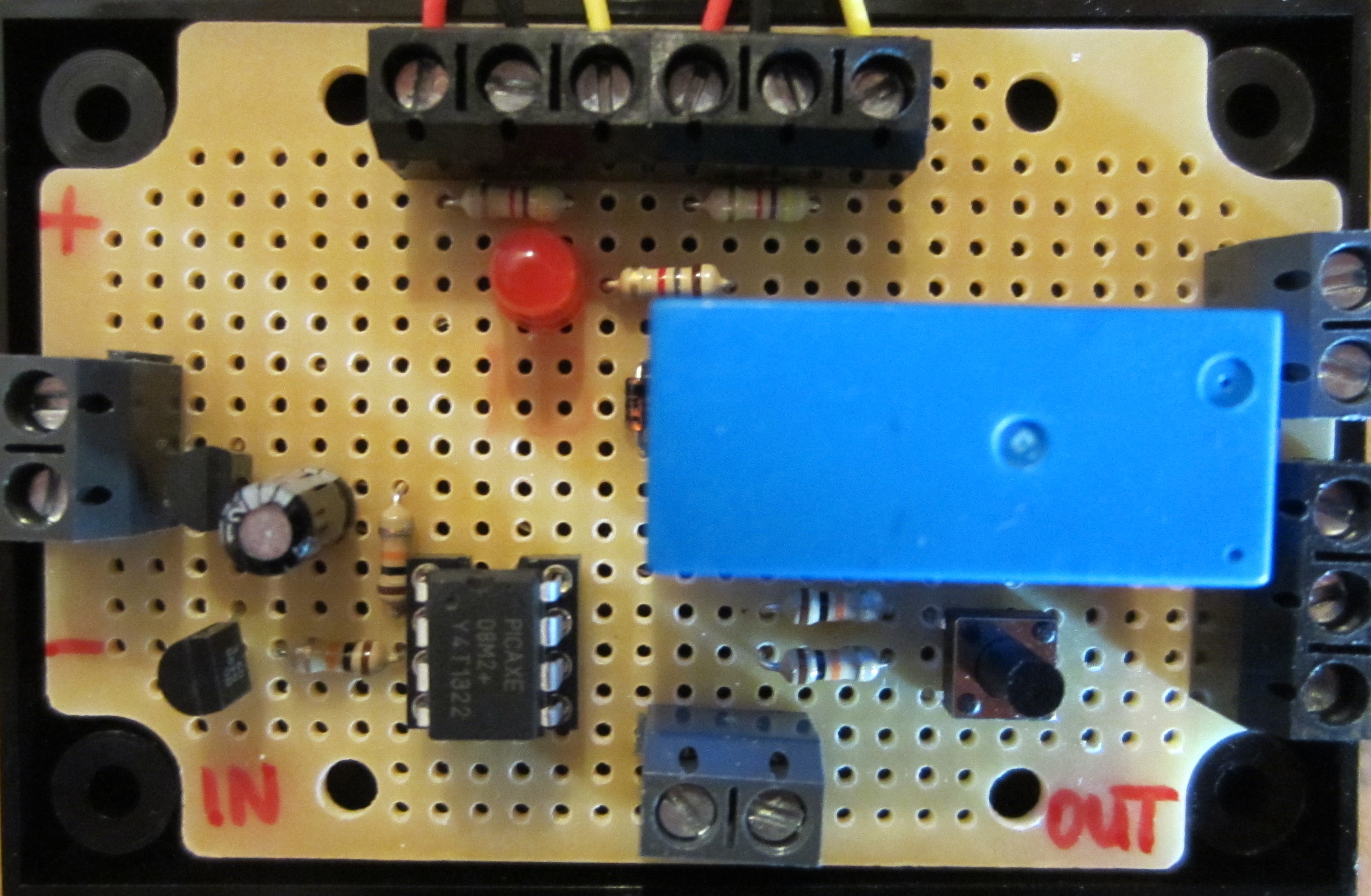
The Arduino Pro Mini (£3) was programmed from a PC via an FTDI breakout board (£5), and connected to an Arduino micro SD module (£1) fitted with a 1GB micro SD card (£3). Note that the unlabelled components in the image above are not required for this datalogger – we just built the controller so that it can later also be used as a low voltage disconnect.
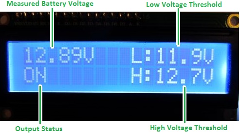
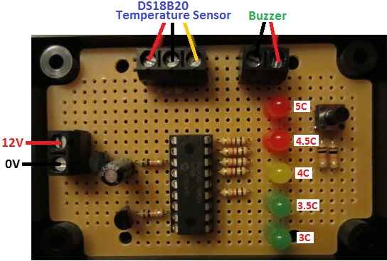
We programmed the Arduino to read in the voltage of a 5Ah 12V SLA (via a 47K-10K voltage divider) and write it to a log file on the SD card once every second. The battery is connected to an 80 Watt PV solar panel via a solar charge controller. The battery is also connected to three 1W LED spotlight bulbs which were left permanently on so that the battery would drain over night and be recharged during the day.
The datalogger was left connected to the battery from around 10:30am one day to around noon the following day in mid-April with blue skies both days.
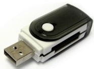
In order to view the data collected on the micro SD card we just needed a USB all-in-one memory card reader (£1). Plug the micro SD card into the reader, plug the reader into a PC via USB, and download the collected data.
The collected data file (which was simply a list of voltages measured to 2 decimal places) was 97070 lines long with a file size of 680 kB. Therefore our 1GB card could have logged the battery voltage once a second for 3-4 years.
Looking through the datalog in a text editor it was obvious that the battery voltage did not change very fast at all. Therefore logging the voltage every second was unnecessary for this application – every 30 seconds or every 60 seconds would have been adequate.
Knowing from experience that plotting 100,000+ data points with Excel is usually an unhappy experience, I first copied the log file over to my Raspberry Pi, and ran the following sed script to create a new smaller file containing just every 60th record from the log file. (This is equivalent to having set up the datalogger to log the voltage once per minute in the first place.)
sed -n '0~60p' logfile.txt > 60slogfile.txt
This command took just 0.24 seconds on the Raspberry Pi (thanks to the raw speed of sed) and I then dropped the new smaller (1617 records) log file into Excel and made the following plot of the results.

The vertical axis shows the measured voltage, and the horizontal axis shows time with the far left being 10:30am on day1 and the far right being noon on day2.
The plot shows how the solar charge controller carries out a bulk charge phase to rapidly charge the battery (peaking at 14.6V) and then maintains a float charge (around 13.6V) during the day while the solar generation far exceeded the charge used by the spotlights. At night the voltage of the battery drops rapidly down hitting a low of 11.95V before the sun rose high enough to start to charge the battery again.
If you need a voltage datalogger like this, a voltage datalogger with a built in low voltage disconnect to protect the battery from being too deeply discharged, or any other kind of single or multi-channel datalogger, please email neil@reuk.co.uk with details of your exact requirements.
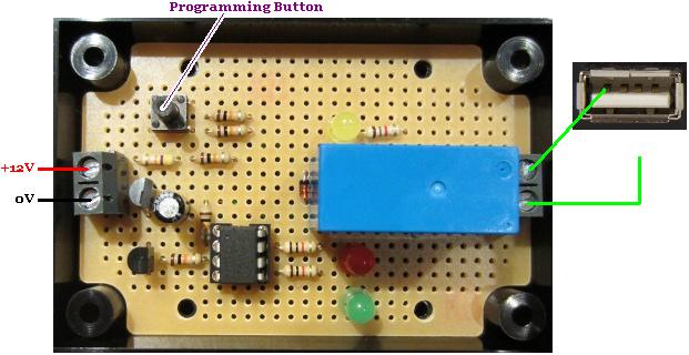
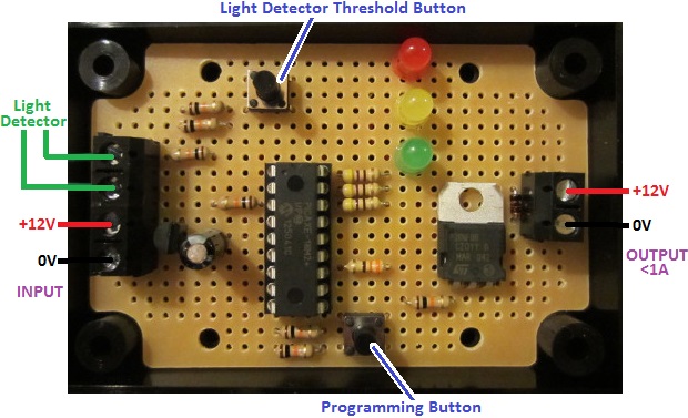 The timer can be programmed with different ON and OFF time durations from 1 second to 99 hours with various modes of operation available. When the time is ON, there is a 12V output (rated at up to 1A) which can be used to control up to 10-12 Watts of 12V devices, or used to switch a relay if higher currents or different voltages are to be switched.
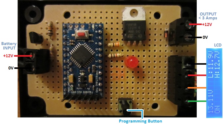
 We will soon be returning to this to look at how batteries can be monitored, solar generation can be monitored, and many other similar projects.