In our article Make a Simple Battery Status Monitor we showed how a few components could be put together to make a very basic battery voltage monitor to give a visual indication of the charge state of a 12V lead acid battery.
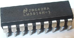
Here we will show you how to make a more advanced battery monitor using 10 LEDs (or an LED bargraph display) and the LM3914 dot/bar display driver (pictured above) to show the battery voltage very accurately.
(Click here to buy an LM3914 Display Driver from around £1.50 each, and here to buy a 10 LED Bargraph for around £2.)
12V Battery Monitor Circuit
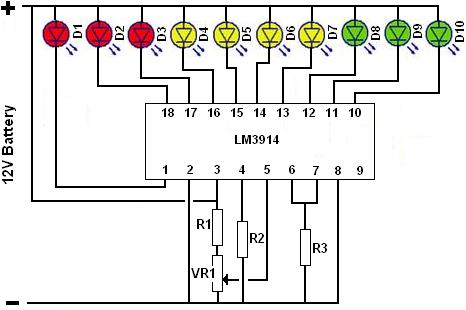
Above is shown the schematic for our 12 Volt battery monitor. The values of the resistors are R1 = 56K, R2 = 120K + 47K, R3 = 3K9 to give us an 11.89V to 12.65V voltage range – i.e. the first red LED (D1) will light up at a voltage of 11.89V which is a virtually empty 12V lead acid battery, and the last green LED (D10) will light up at a voltage of 12.65V corresponding to a full 12V lead acid battery. The other LEDs will turn on one by one as the measured voltage increases through the range.
To calibrate the monitor, connect it to 12.65V and adjust the 10K potentiometer (VR1) until the last green LED turns on. With the resistor values used, you will just need to check that the first red LED turns off as it should at 11.89V.
The LM3914 has two modes – DOT and BAR. With DOT mode (as used in our example above) only one LED is on at a time. With BAR mode – achieved by connecting pin 9 to the incoming positive voltage – all LEDs up to the measured voltage are on at the same time like a bar graph.
In DOT mode the circuit shown above would draw under 10mA. In BAR mode the current consumption would be increased by an amount depending on the number of LEDs turned on up to around 100mA when the battery is full.
To change the brightness of the LEDs, R3 can be changed. Increasing the value reduces the brightness (and also reduces current consumption), decreasing the value increases the brightness (and also increases the current consumption). Replacing R3 with a variable resistor in series with a 1K resistor enables the brightness of the LEDs to be easily changed for example for indoor or outdoor use.
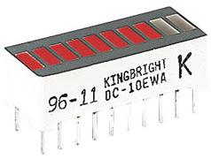
Instead of using 10 individual LEDs, an alternative is to use an LED bargraph display such as that shown above. It is basically 10 LEDs packaged nice and small and tidy. These are available in a range of different colours, sizes, and number of LEDs.
Changing the Battery Monitor Voltage Range
Changing the voltage range for use with different types of battery or any other reason is very easy. The upper limit is set with the 10K pot as during calibration – just connect the desired upper limit voltage (above which the last green LED will turn on) to the monitor using a battery at that votlage or ideally a variable voltage power supply, and adjust the 10K pot until the last green LED just turns on.
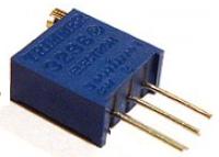
Adjusting the lower limit is a bit trickier. Replace the R2 resistor(s) with a 200K potentiometer (as shown above), connect the desired lower limit voltage to the monitor and adjust the 200K potentiometer until the first red LED just turns on. You can leave this 200K pot in place, but for reliability it is better to measure the resistance across the two potentiometer terminals connected in place of R2 and then replace the potentiometer with fixed resistors totalling the measured value.
The above steps are made very much easier if you have access to a variable voltage power supply.
More Information
Click here for the LM3914 Datasheet for more technical information on using this display driver chip.