Double Controller for De-Stratification

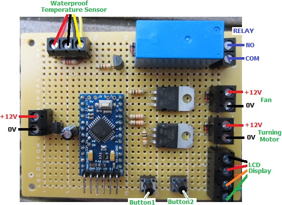
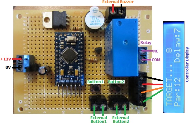
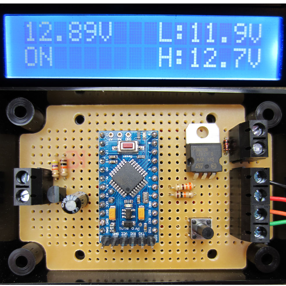
Pictured below is a controller we recently made to de-stratify hot water cylinders. Stratification is the layering of water of different temperatures within a tank or cylinder. It leads to the problem of having a thin layer of extremely hot water at the top sitting above a quantity of much cooler water. Therefore any thermostats or temperature sensors on the cylinder will only see cool water (making the system inefficient), while dangerously hot water comes out of the hot tap.

Double de-stratifying Circuit for hot water cylinders
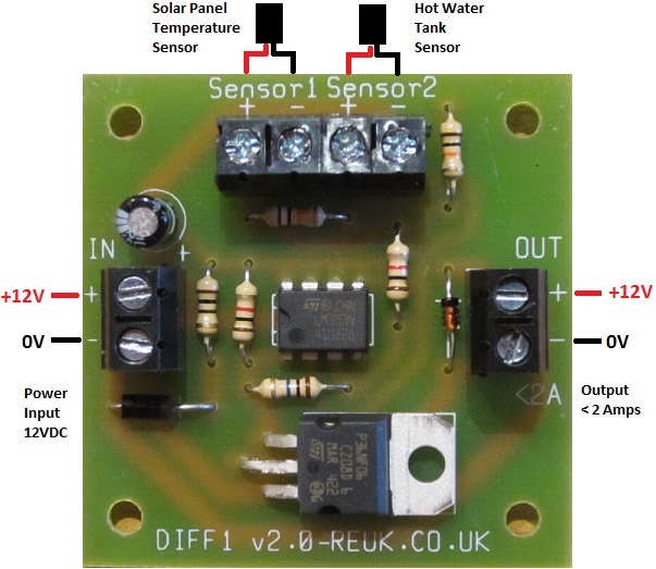
This double controller is basically two of our 2013 solar water heating pump controllers put onto one board with a single power input. There is a top sensor and a bottom sensor for each cylinder to be de-stratified. (We used precision LM335Z temperature sensors for this project)

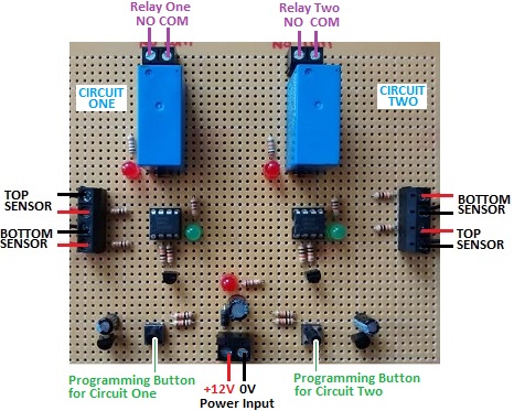
When the top sensor is measured to be a user set number of degrees (diffON) hotter than the bottom sensor, a circulation pump is turned on via the relay to mix the top layer of hot water into the cooler water below. This heats up the cooler water and cools down the hotter water giving a more consistent temperature throughout. The pump stays on until the difference between the top and bottom sensors has fallen below a second user set number of degrees (diffOFF).

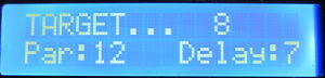
With this particular controller diffON is set in steps of five degrees whereas diffOFF is set in steps of single degrees.

If you need any kind of temperature sensing relay controller or similar, email neil@reuk.co.uk with details of your exact requirements.

PIR Motion Sending Relay Controller for Security

Pictured below is a PIR sensor based security system relay controller we recently made.

PIR Motion Sensor Relay Board for Security SystemWe make a lot of devices to interact with and monitor motion sensors – for example our user programmable PIR Relay Timer  designed for use with standard domestic PIR motion sensors such as the popular Honeywell IS-215T.

This controller pictured has a few added features specific to the requirements of the customer. A switch has been fitted so that the system can be armed easily when required. When the switch is closed, the user has 10 seconds to get out of the range of the motion sensor. While motion is being detected, the red LED is on, and after motion is first detected the yellow LED turns on and stays on. 10 seconds after motion is first detected the connected siren and strobe light are activated. Therefore the user has 10 seconds upon entering the protected area to disarm the system by turning off the switch (the location of which is of course unknown to intruders).

The user can programme in the duration that the siren and strobe lights will be on after motion is detected.

If you require any kind of system to interact with one or more PIR motion sensors, email neil@reuk.co.uk with details of your exact requirements.

New REUK Differential Thermostat PCB

Pictured below is the latest (November 2014) version of our Differential Thermostat designed to be used in simple solar water heating systems, fan controllers moving warm air to cooler areas, and many other applications.

REUK Differential Thermostat - for solar water heating and fan control etc.This device is based around this solar water heating pump controller design which we have been selling now for over 8 years. When the left hand side temperature sensor is measured to be hotter than the right hand side sensor, the up to 2 Amps output is turned on, and remains on until the temperature difference between the two sensors has fallen to zero.

Connection diagram for REUK Differential Thermostat - new version Nov 2014This output can be used to directly power small pumps or fans etc, or can be used to switch a relay which can in turn switch high current or higher voltage devices.

Click here for more details and/or to purchase this new Differential Thermostat from the REUK Shop.

Controller for Poultry Incubator

Pictured below is an automatic controller for a poultry incubator. The eggs in this incubator must be kept within a tightly regulated temperature range, they need to be automatically turned at regular intervals, and there is also a fan to be controlled.

thermostatic poultry incubator control boardThe owner of this incubator would like the temperature of the eggs to be kept between 37 and 37.5 degrees Celcius, so there is a heating element which is switched by an on board relay following the temperatures measured by a DS18B20 waterproof sensor.

The eggs are to be turned every 30,45,60, or 75 minutes, and to do this the motor must run each time for a few seconds. Both of these timing intervals can be set by the user.

The fan has three modes of operation – on, off, or automatic, and in automatic mode the user can select an interval of 5, 10, or 15, etc minutes on and minutes off repeating.

Display for thermostatic poultry incubator controllerAll of the current settings and system status are shown on a backlit 16×2 LCD display (see above), and all user settings are programmed using this display and the two buttons on the controller board.

If you need a controller of this type, please email neil@reuk.co.uk with details of your exact requirements. For details of an alternative incubator controller which also controls humidity, click here: Poultry Egg Incubator with Humidity Sensor.

Automatic Shooting Target Time Controller

Pictured below is a controller designed for competitive shooters to automatically turn targets on the range to face to and away from the shooters for the required length of time.

shooting-range-target-controllerThe targets are controlled by air solenoids. When these are energised the targets face away from the shooter, so our controller has a relay with NC and COM connections (normally connected). When the relay is energised, the NC-COM connection breaks and the targets turn to face the shooter.

After pressing a button to start the timer, there is a user selected delay of 3 or 7 seconds. Then the relay is energised to turn the targets to face the shooters and a buzzer sounds for half a second. The targets are kept facing the shooters for a user selected ‘par’ time of 1,2,3,4…15, 25, 35, 90, 165, or 210 seconds. Then the relay is de-energised, the targets turn away, and the buzzer again sounds for half a second. The system then resets ready to be used again.

Pressing the other button acts as an override so that the targets can be kept facing the shooter until the button is pressed again to cancel the override.

range-controller-targets-turnedAn LCD display is provided to make setting up the device with the required delay time and par time easy, and also to show a countdown of the number of seconds remaining during the two countdowns when the system has been triggered. It also constantly shows the current delay and par time settings to make the system easy to use.

We have added screw in terminals to the board so that a louder external buzzer/siren can be added, and so that external buttons can be mounted if the controller is to be housed in a waterproof box etc.

If you require a controller of this type (here is another of the competitive shooting timers we have made recently), please email neil@reuk.co.uk with details of your exact requirements.


DS18B20 Temperature Measurement with Spark Core

In our blog post Spark Core Introduction and First Impressions we introduced Spark Core – a Wi-Fi enabled Internet of Things device which can be programmed like an Arduino and accessed via the internet.

Spark Core Wi-Fi Open Source IoT development board

Of most interest to us at REUK is using Spark Core to enhance our range of solar water heating controller adding datalogging and internet functionality. Therefore we want to access temperature readings from DS18B20 digital temperature sensors of the type used in our 2014 Solar Water Heating Pump Controller connected to Spark Core.

As a test we connected a DS18B20 temperature sensor to the Spark Core. Pin 1 of the sensor connects to GND, Pin 3 to 3.3V, and Pin 2 to a digital pin on Spark Core – we randomly chose D2. Finally we connected a 4K7 resistor across Pins 1 and 3 of the sensor and entered the following code via the Spark IDE to flash to the Spark Core:

#include "spark-dallas-temperature/spark-dallas-temperature.h"
#include "OneWire/OneWire.h"
#define ONE_WIRE_BUS 2
OneWire oneWire(ONE_WIRE_BUS);
DallasTemperature sensor(&oneWire);

float temperature = 1.0;
char myStr[10];

void setup() {
 Spark.variable("read", &myStr, STRING);
 sensor.begin();
 sensor.setResolution(12);
}

void loop() {
 sensor.requestTemperatures();
 temperature= sensor.getTempCByIndex(0);
 sprintf(myStr,"%.3f",temperature);
}

At the time of writing (August 2014) it is not possible to have a Spark.variable which is a float – the code just will not compile – so the temperature measurement from the sensor (which is a float/double) must either be saved as an integer (losing accuracy due to rounding) or be converted into a string (which is what we did above to three decimal places with the sprintf function) so it can be accessed remotely.

We then wrote the following Python script on an internet connected Raspberry Pi to grab the temperature measurement once every minute and to append it to a text file for datalogging and later analysis:

#!/usr/bin/python

import urllib2
import json
import time

var = 1
while var == 1:
   response = urllib2.urlopen('https://api.spark.io/v1/devices/YOURDEVICEID/read?access_token=YOURACCESSTOKEN')
   html = response.read()
   reading = json.loads(html)
   temperature = reading['result']
   with open("core-temp-log.txt", "a") as myfile:
      myfile.write(temperature)
      myfile.write('\n')
   myfile.close();
   time.sleep(60)

The string variable read is the string conversion of the value read in by the temperature sensor.

Having got the Spark Core successfully reading data from a DS18B20 it is possible to fully replicate our Arduino based solar water heating pump controllers with the added benefit of internet connectivity and effective remote datalogging.

See our Raspberry Pi related articles Publish Temperature Sensor Readings to Twitter and Temperature Logger with Xively to find out how to automatically publish your collected data to the internet – either as a Twitter feed or with Xively as an online datalogger with graph plotting etc.

Nabduino Remote Access Board

Pictured below is Nabduino – an “open source peer-to-peer remote access embedded board with a user modifiable web-interface developed by Nabto“.

Nabduino board

This small board (available to purchase here: buy Nabduino) can be accessed via a direct encrypted connection through a firewall without the need to change the firewall settings of your router.

If for example you set up a server on a Raspberry Pi – that server will only be visible on your local network unless you change settings on your router to make it visible world wide. If your that server is not set up correctly, then your whole network is at risk – therefore this is best left to experts. Having set up that server, you then need either a static IP address (not usually free of charge) or set up some web services (sometimes free, sometimes not), so that you can find your server when you are outside the local network.

The Nabduino board makes things a lot easier and safer than all that trouble. You simply connect an ethernet cable connected to your local network to the board, connect power to the board, and that is it. Each Nabduino board has a unique ID, and there is a simple web interface which gives you access to the board and its sensors etc accessible from anywhere in the world at XXXX.nabduino.net where XXXX is the ID of your board.

web interface for nabduino board

Via the simple web interface (pictured above), the state of the on board button can be viewed, an on board LED can be controlled, the temperature of the microprocessor can be monitored, five PWM outputs can be set with values from 0-255 for dimming lights or motor control, the status of six analog inputs can be viewed, and thirteen digital pins can be set to input or output and be controlled remotely.

As it stands, Nabduino could be used for simple remote control of a home via relays connected to digital outputs – for example, turning on some lights when you are away from home using your mobile phone or PC. Similarly, very basic home monitoring could be achieved with sensor switches connected to digital inputs. However, much more powerful things can be achieved connecting the Nabduino to an Arduino board so that the Arduino can respond to digital and PWM signals from the Nabduino and carry out any complex logic.

We will be looking at the Nabduino board in much more detail soon. Until then, click here to find out more about Nabto.com.

New Raspberry Pi Model B+

We have just received our new Raspberry Pi Model B+. This is not the Raspberry Pi 2 or C (which is likely to be released in 2017), but is instead a Model B with a few very useful changes and additions.

Raspberry Pi Model B+

The biggest addition is a further two USB ports bringing the total up to four USB 2.0 ports. This is particularly useful since a mouse and keyboard would use all the ports on the Model B leaving no ports free for thumb drives, and other peripherals without the use of a secondary powered USB hub.

Raspberry Pi B+ can now be configured to output a total of 1.2 Amps in total (0.6A by default) from its USB ports (assuming a good quality 2A power supply is used). Therefore external hard drives can be used without the need for a powered hub.

The original SD card slot has been replaced by a micro-SD card which means no more SD card sticking out of the Raspberry Pi, and it is easier and cheaper to buy micro-SD cards.

A further 14 GPIO pins have been added to the 26 pins found on the Raspberry Pi Model B for a total of 40 GPIO pins for hardware projects. The layout of the first 26 pins has been kept the same for backwards compatibility.

Finally, power consumption has been reduced a little, sound quality has been improved with the audio connector changed to integrate composite video, and the overall layout of the board has been changed and mounting holes added to the corners of the board.

The processor and RAM (512MB) remain unchanged.

We will be doing some interesting projects with our new Raspberry Pi B+ over the next few weeks and months to make use of the additional functionality offered by this new model.

Pyboard Python for Microcontrollers

Pyboard python for microcontrollersPictured above is the Pyboard – an open source prototyping platform designed and manufactured in the UK. This board with its ARM microcontroller (STM32F405 clocked at 168MHz) is programmed using micropython a low memory usage version of the Python 3 scripting language.

The board has LEDs, microswitches, a built in accelerometer, and 30 general purpose IO connections (including 4 PWM, 14 ADC, I2C, and SPI pins) for connection to external components and analogue/digital sensors for your projects.

The board has 1MB of on board flash memory, 192KB of RAM, and also a micro SD card slot which can be used to store scripts and hold project generated data. It has a built in USB interface.

Pyboard fits in the marketplace somewhere between Raspberry Pi and Arduino. A Raspberry Pi is a full computer which means that it can be complicated to use, power hungry, and large in size. An Arduino is simple to use, has lots of useful GPIO and shields, and they are available in small versions, but they are not very fast and scripts need to be compiled on a PC before loading them to the Arduino. Pyboard is perfect for processor intensive stand alone projects – particularly for anyone who already has experience programming with Python.

Pyboard is just 33 x 40mm in size and weighs just 6g.

The official Micro Python website is here, and the tutorial which shows how to get strarted with Pyboard and Micro Python is here: Micro Python Tutorial.

New REUK Low Voltage Disconnect with Display

Pictured below is the new REUK Programmable 12V Low Voltage Disconnect with LCD Display. This device allows batteries and battery banks to be protected from being too deeply discharged, and also enables battery  monitoring.

reuk low voltage disconnect with displayFor full details, instructions for use, and to purchase, click here: REUK 12V LVD with LCD). It has been added to the existing low voltage disconnect circuits in the REUK Shop.