Raspberry Pi 3 Model A+

Raspberry Pi 3 Model A+

Today (November 15th 2018) the new Raspberry Pi Model 3 A+ was released, four years after the release of the original Raspberry Pi Model A+.

The new A+ is a physically smaller (65mm × 56.5mm compared to 85.6mm × 56.5mm) and cheaper (US$25 compared to US$35) version of the Raspberry Pi Model 3 B+ with slightly reduced features.

The A+ has just one USB 2.0, the B+ has four. The A+ has half the LPDDR2 RAM of the B+ with 512MB compared to 1GB.  And, the A+ has no ethernet port whereas the B+ has gigabit ethernet connectivity.

The Raspberry Pi Model 3 A+ and B+ share the same 1.4GHz quad-core Arm Cortex A53 processor, and the same WiFi and Bluetooth connectivity.

Arduino Two Channel Thermometer with Display (Full Code)

Pictured below is a two-channel thermometer we recently built for a customer. This device takes inputs from two ds18b20 temperature sensors and displays their measured temperatures on a 1602 LCD display module. The thermometer is built around an Arduino Pro Mini.

Arduino double thermometer with lcd display - full code provided

Below is the full Arduino sketch (code) for our device.

See this guide to Connecting an I2C Display to Arduino for the LCD connections. We have added the necessary 3k3 pull up resistors between pin A4 and 5V, and pin A5 and 5V – click here to read about I2C Pull Up Resistors. We have also used an external 5V regulator rather than relying on the 5V regulator built into the Arduino Pro Mini, and added reverse polarity protection on the input with a 1N4001 diode.

// © reuk.co.uk - 2018
// Double Thermometer with Display.

// For the DS18B20 temperature sensors.
#include <OneWire.h> // (https://github.com/PaulStoffregen/OneWire)
#include <DallasTemperature.h> // (https://github.com/milesburton/Arduino-Temperature-Control-Library)

// Data wires are plugged into pins 2 and 3 on the arduino.
#define ONE_WIRE_BUS 2
#define SECOND_BUS 3

// For the 1602 LCD module.
#include <Wire.h>
#include <LCD.h>
#include <LiquidCrystal_I2C.h>
#define I2C_ADDR 0x27 // Note that some modules have address 0x3F

#define BACKLIGHT_PIN 3
#define En_pin 2
#define Rw_pin 1
#define Rs_pin 0
#define D4_pin 4
#define D5_pin 5
#define D6_pin 6
#define D7_pin 7
LiquidCrystal_I2C lcd(I2C_ADDR,En_pin,Rw_pin,Rs_pin,D4_pin,D5_pin,D6_pin,D7_pin);

// Setup a oneWire instances to communicate with OneWire devices.
OneWire oneWire(ONE_WIRE_BUS);
OneWire secondWire(SECOND_BUS);

// Pass our oneWire reference to Dallas Temperature.
DallasTemperature sensor1(&oneWire);
DallasTemperature sensor2(&secondWire);

float sensorOneTemperature = 0.0;
float sensorTwoTemperature = 0.0;

void setup(void)
{
 // Start up the temperature sensor library.
 sensor1.begin();
 sensor2.begin();
 
 // Set the temperature sensor resolutions to 11 bit
 // ADC (12 bit is much slower but higher resolution).
 sensor1.setResolution(11);
 sensor2.setResolution(11);
 
 // Initialise the LCD.
 lcd.begin (16,2); // For a 16x2 character LCD
 // Switch on the LCD backlight.
 lcd.setBacklightPin(BACKLIGHT_PIN,POSITIVE);
 lcd.setBacklight(HIGH);
 // Clear the LCD screen.
 lcd.clear();
}

void loop(void)
{ 
 // Read in the temperatures of the two sensors.
 sensor1.requestTemperatures(); // Read temperature of sensor1
 sensorOneTemperature = sensor1.getTempCByIndex(0);
 sensor2.requestTemperatures(); // Read temperature of sensor2
 sensorTwoTemperature = sensor2.getTempCByIndex(0);

 // Display the temperatures of the sensors on the LCD.
 displayTemperatures();
}

void displayTemperatures(){
 // Display sensor1's temperature.
 lcd.setCursor(0,0);
 lcd.print(" T1: ");
 lcd.print(sensorOneTemperature,2);
 lcd.print((char)223);
 lcd.print("C ");
 
 // Display sensor2's temperature.
 lcd.setCursor(0,1);
 lcd.print(" T2: ");
 lcd.print(sensorTwoTemperature,2);
 lcd.print((char)223);
 lcd.print("C ");
}

If you need any kind of bespoke thermometer or thermostat, please email neil@reuk.co.uk with details of your specific requirements.

Hen House Door Controller with Manual Override Buttons

Pictured below is a new hen house door controller we recently made for a customer.hen house door controller with manual overrideOur most common design for a door opener/closer is our Dawn Dusk Henhouse Door Controller – a device which uses a couple of roller limit switches to keep track of the position of the door, and a light detector to detect dawn and dusk.

This new device is designed for operation with an aluminium screen door opened and closed by a linear actuator which has its own internal limit switches. At dawn, voltage is supplied to the actuator for one minute giving the actuator time to fully open the door with no worries that it will overrun thanks to the limit switches. At dusk, reverse polarity voltage is supplied to the actuator one one minute to close the door. The user can set the ambient light level threshold at which the door will open or close.

A further requirement for this controller was the ability to manually open or close the door at any time in order to give access to the chicken run. For this the user can select manual mode, and use the lower door or raise door buttons when they need to use the door. The controller keeps track of the position of the door during manual operation which is vital as there are no limit switches connected to the controller to tell it where the door is. On board buttons are available, but also screw in terminals so that external push-to-make buttons can be more conveniently located.

If you need any kind of door controller, please email neil@reuk.co.uk with details of your requirements.

Door Controller Instructions

Light Detector

With the board connected up as per the diagram, the first step is to set the light detector threshold. The light detector is not waterproof, so it must be protected from rain, but also positioned so that it is exposed to natural light. The leads to the light detector can be extended to get it in an optimal safe location.

In the late afternoon / evening when the ambient light is at the level below which you want the door to be closed, press and hold the calibrate light detector button for more than one second. The red and green LEDs will then alternately flash for a few seconds and the current measured light level will be saved in memory as the night-dawn and day-dusk threshold.

Manual Operation

If the yellow LED is on, the device is in manual mode. To toggle between manual and automatic mode, press the choose auto/manual button.

In manual mode, pressing the manual lower door button will see power output to the actuator for one minute to close the door. (If during that one minute, you press the manual raise door button, power to the actuator will be cut leaving the door somewhere between open and closed.) Similarly, you can manually open the door by pressing the manual raise door button.

If you find that pressing the button to close the door instead opens the door, reverse the polarity of the power connections to the actuator.

Automatic Operation

When initially powered on, the device assumes that it is day time and the door is open. (If you connect the power at midday with the door closed for example, the door will not open until the following morning unless you manually open it.)

When it gets ‘dark’ – light level measured to be below the user set threshold – the red LED will turn on. After 10 seconds of continuous ‘darkness’, the door will automatically be closed with power supplied to the actuator for one minute and the actuator’s internal limit switches preventing the door from overrunning. Now the device will sleep for two hours – red and green LEDs alternately flashing – so that no false dawns are detected if the skies suddenly brighten.

After the sleep, it will now be very dark. The device will wait through the night until dawn – light level measured to be above the user set threshold – and then turn on the green LED. After 10 seconds of continuous ‘light’, the door will automatically open, again followed by a 2 hour sleep to prevent the detection of a false dusk if clouds cover the sun.

Formula 1 Race Starting Lighting Timer

formula 1 racing timerPictured above is a timer we recently built for a customer which will be used in a Formula 1 style race start lighting gantry. This gantry will be fitted at the top of a slope with toy cars held by a small gate latched up by a small solenoid with a spring loaded core. When the race is to start, the solenoid is energised which drops the gate allowing the cars to roll down the slope in their race.

In the photograph, five red LEDs are temporarily attached to the timer board for testing, but these will be mounted into the gantry across the track when it is finished.

When the user presses the button, the LEDs follow the standard F1 race start sequence – each red LED turns on in sequence with a one second interval. As each LED turns on, an on board piezo buzzer briefly pips. Then, when all five LEDs are illuminated, there is a random time interval of between 1 and 3 seconds before all the LEDs are turned off.

formula 1 race starting gantryThe lights turning off indicates that the race is to start. The buzzer sounds for 1 second, while the on board relay energises for 1 second to energise the solenoid and start the race.

Another Race Starting Timer

Pictured below is another similar race starting timer we made which controls three powerful lights via external relays.

3-light-formula-one-start-timerWhen the start button is pressed, there is a five second delay, then the three lights turn on one by one at one second intervals. After a random 0.5 to 4-5 second delay, the lights all turn back off.

If you need any kind of bespoke timer or controller, please email neil@reuk.co.uk with details of your requirements.

Solar Water Heating Pump Controller with Timer Override

solar water heating pump controller with maximum temperature and timer override

Pictured above is a solar water heating pump controller we recently made for a customer. This device is based around our popular 2016 solar water heating pump controller with display and datalogger, but has some added features.

The first added feature is a maximum temperature override. As this device will be used for solar heating of a swimming pool, we added user programmable maximum pool temperature override. If the pool starts to get too hot, the pump bringing hot water from the solar panel will not be run again until the pool temperature has fallen by at least two degrees Celcius.

The second added feature which we have not been asked for before is a timer override. The user of this device only wants the pump to be allowed to run between 10am and 4pm, so we have added a 12V programmable digital timer so that the user can set the times of operation of the heating system.

If you need any kind of pump controller or timer, please email neil@reuk.co.uk with details of your requirements.

Raspberry Pi Home Automation with Machinon

Pictured below is Machinon, hopefully soon to be released industrial-grade hardware originating from a community project, and designed to manage home and small business automation with a Raspberry Pi.

machinon home automation iot raspberry piThis smart home solution adds smart IO to a Raspberry Pi – 16 digital inputs, 16 digital outputs, and 8 analogue inputs.

The digital inputs can be used as pulse counters (for kWh meters etc) or to detect status changes (doors opening and closing, buttons being pressed, motion sensors triggered etc).
The analogue inputs (0 to 20mA, 4 to 20mA, and 0 to 10V input with 14bit resolution) can be used to measure currents and voltages, light levels, temperatures, and more.
The digital outputs each supply up to 500mA which can be used to switch high voltage and high current appliances via a relay, or directly power low current low voltage devices.

Machinon utilises two ATxmega microprocessors which take care of all the complex pulse counting, timing, analogue measuring, and data collection. The Raspberry Pi then simply communicates with Machinon via UART (serial port) to grab data and control and configure the smart IO.

machinon smart home prototype internals

Machinon is designed to interface with many open source home automation software packages including Domoticz, openHAB, and HomeGenie so the overall user experience should be relatively simple.

The price of this device is likely to be around £200 plus the cost of a Raspberry Pi and microSD card to go in it. Therefore, probably under £250 all in including delivery.

machinon smart home with raspberry pi

For more information, click here to visit the Machinon website.

2x12V 24V Battery Bank Low Voltage Disconnect

24V battery bank low voltage disconnect LVD with dual battery measurementPictured above is a low voltage disconnect (LVD) we recently made for use with a 24V battery bank comprising two 12V batteries. These two batteries do not equalise well (i.e. they do not hold the exact same charge or show the same voltage), and so this low voltage disconnect has to look at both batteries independently and take actions based upon the measurements of the weakest battery.

This device is based around our OLED display 12V LVD with some major modifications. The batteries are connected in series to make a 24V bank. The device measures the voltage of the whole battery bank and also measures the voltage of the first 12V battery. The second 12V battery voltage is then calculated by subtracting the first 12V battery voltage from the 24V battery bank voltage.

OLED display on 24V battery bank LVDThe OLED display on the low voltage disconnect shows the two battery voltages which make up the bank, the status of the LVD, and the voltage threshold (user programmable) at which the status of the LVD will next change (turn off the output if it is on, turn it on if it is off) depending on the charge level of the two batteries in the bank.

If the voltage of either battery in the battery bank falls below the low voltage threshold set by the user, the output will be turned off cutting the power to any devices being powered by the battery bank. When both of the batteries in the bank then reach a voltage in excess of the high voltage threshold set by the user, the output is restored reconnecting power to the devices powered by the battery bank.

If you need any kind of low voltage disconnect, please take a look at our range of LVD products, and email neil@reuk.co.uk if you have any special requirements.

Dual Pulse Spot Welder Timer Controller

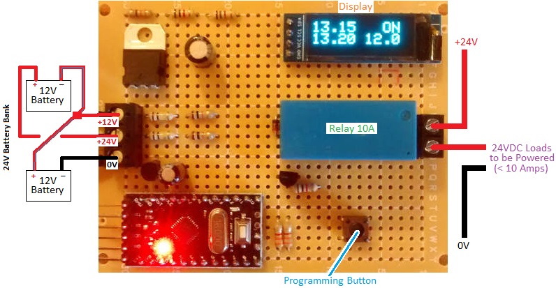
Pictured below is our popular 12VDC dual pulse spot welder timer controller which we designed, build, and sell.dual pulse spot welder controller

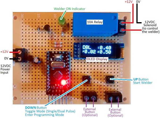
Spot welding (resistance spot welding – RSW) is used to join metal surfaces by passing a large electric current through them. Because of the heat generated by the resistance to the electric current, the contacting metals melt together forming a weld at the spot through which the current is passing.

In order to get good clean reliable welds and not to burn holes through the metal, it is essential that the pulse of electric current is of a suitable duration which depends on the types and thicknesses of the metals to be welded as well as many other factors. Therefore an accurate timer controller is required for consistent welds.

For the best spot welds, a dual pulse controller is used in which the electric current flows for a time (pre-weld), then there is a brief pause, and then electric current flows again (welding). The first pulse clears away any plating or surface oxidation, and then the second pulse welds the now clean base materials together. Using a dual pulse welder also reduces spitting.

REUK Dual Pulse Spot Welder Controller

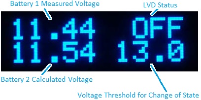
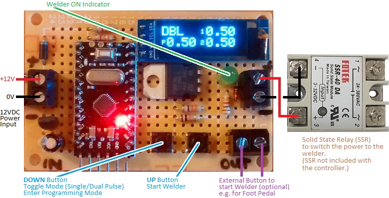
Our controller offers two modes of operation: single pulse mode and dual/double pulse mode. Pictured below is a view of the built in OLED display when in dual pulse mode.

dual pulse spot welder display

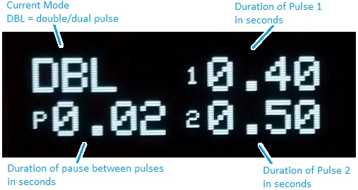
The user can set the durations of Pulse 1, the pause time, and Pulse 2 in 0.01 second steps between 0.01 and 1.99 seconds.

single pulse operation of spot welder

In single pulse mode, the duration of just one pulse has to be set by the user. (A future update of this device will probably include up to 10 user-programmable presets for increased convenience.)

setting spot welder pulse duration

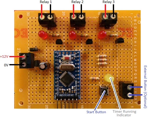
On board buttons are provided for toggling between the single and double pulse modes, entering programming mode to set the timings, and making a spot weld with the displayed settings. Screw in terminals are provided so that external buttons can be connected – for example a foot pedal to make a weld with your hands free.

This version of the welder controller is fitted with a 10A relay which can be used to power a < 5A rated solenoid which in turn switches the welder.

Buy a Welder Timer Controller for Your Relay

For any type of welder timer controller, please email neil@reuk.co.uk with details of any special requirements. Our controller as described above is available at £21.95 plus postage.

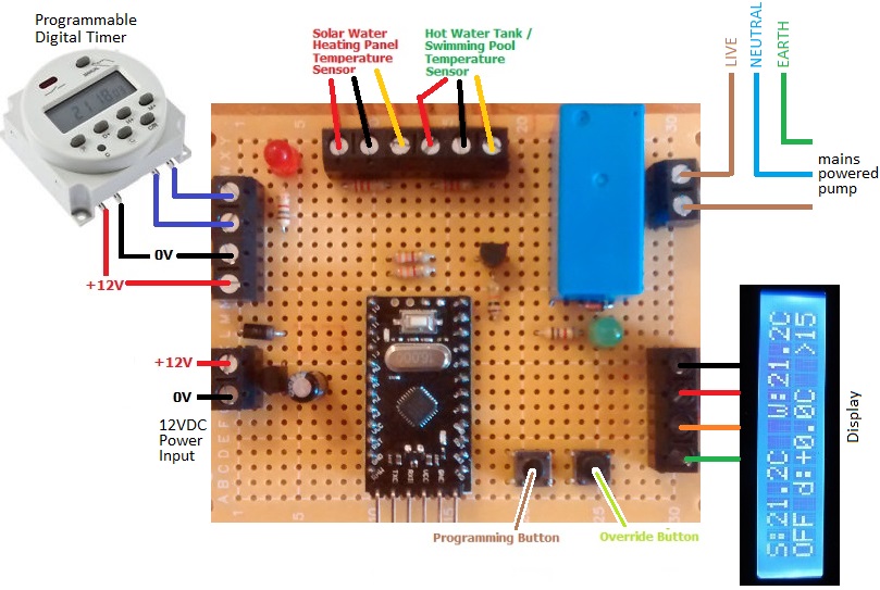
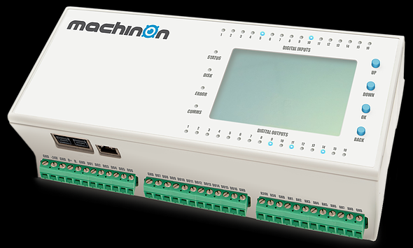
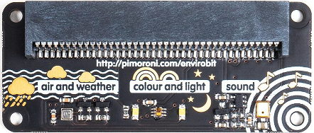
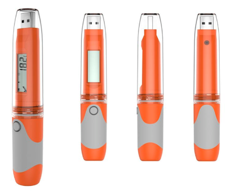
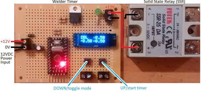
If you require a timer which will be switching more than 10 Amps of current for your welding setup, then we also make the alternative devices pictured below which have a 1 Amp 12V output for connection to your own solid state relay (SSR) or mechanical relay. These are available for £19.95 plus postage – no relay included. Click here for a source of solid state relays.

reuk dual pulse welder timer controller for solid state relay

dual pulse welder timer with solid state relay (ssr)

If you require a bespoke device which pulses the welder with very brief times and higher time resolution – e.g. 0.001s – 1.999s instead of 0.01-1.99s – we can modify the above photographed timer controller…but only for use with a solid state relay (since SSRs can switch in 1ms (0.001s) rather than the 10’s of milliseconds it can potentially take a mechanical relay to switch). Contact us with details of your specific requirements for a quotation.

Dual Pulse Spot Welder Timer Instructions

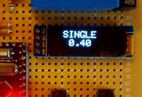
There are two buttons on the controller. If you press the ‘down’ button, you can toggle between single pulse and dual/double pulse operation. The display will change to show which mode you are in: SINGLE or DBL (double) as well as showing the durations currently programmed into the device.

If you press and hold the down button for more than one second, the display will show SET TIMERS. If you are in single pulse mode, you can now set the single pulse duration. If you are in double pulse mode you can now set the durations of pulse 1, the pause time, and pulse 2. The top line of the display will show what is currently being programmed (Time 1, Pause Time, or Time 2), and the bottom line will show the current value. Use the up and down buttons to increase or decrease the displayed value (within the range 0.01s to 0.99s). Five seconds after you last touched a button, the top line of the display will show -SAVED- and the value will be saved in long term memory (still available the next time you power on the controller). If you are in double pulse mode, you will now be asked to set the pause time and the duration of the second pulse in exactly the same way that Time 1 was set. (When using the up and down buttons to increase or decrease a time value, you can press and hold the button to move faster through the numbers.)

If you press the up button, the controller will run. The relay will close for the duration of Time 1 and then open again. If you are in double pulse mode, it will then remain open for the duration of Pause Time and then close for the duration of Time 2.

In addition to the buttons on the controller board itself, screw in terminals are provided to which you can connect external buttons of your choosing – e.g. a foot pedal operated button, or a larger hand operated button etc for your own convenience.

enviro:bit sensor for micro:bit

enviro:bit from pimoroni for micro:bitPictured above is the new enviro:bit for micro:bit from Pimoroni – available for £20. This device has a collection of sensors which can add be read easily from  Microsoft MakeCode Editor or directly via MicroPython for more advanced projects and programmers.

There are three sensors in total. A BME280 atmospheric sensor which provides temperature, humidity, and air pressure measurements, a TCS3472 colour and light sensor, and a MEMS microphone for sound.

micro:bit plugged into enviro:bit to use sensors

The micro:bit simply plugs into the enviro:bit, and once you have added the required code library or libraries (for MakeCode Editor and/or Mu Code Editor) the sensors can be read, data collected, and displayed on the LED matrix etc.

Click here for more information: buy enviro:bit from Pimoroni.