REUK.CO.UK
The Renewable Energy Website
This is the printer friendly version of the Greenhouse Heatsink Connection Diagram article from the Renewable Energy Website REUK.co.uk.
Click here to print
Printed at 01:26pm 13th June 2026
Greenhouse Heatsink Connection Diagram
Putting together a solar powered greenhouse heatsink system
In our article Solar Greenhouse Heat Sink (1) we introduced a simple method of keeping a greenhouse frost free at night, and also a little cooler in the day when it can otherwise get too hot on sunny days even in the winter.
In this article we will look in more detail at how the electrical (2) part of the system is put together and how the solar panel, battery, and fan should be selected.
The Fan
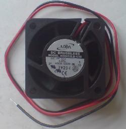
Pictured above is a 12V DC Fan which is rated at 0.070 Amps (0.84 Watts). Available in the UK for around Ł5.00, such a fan is perfect for this application. With brushless contacts and high quality bearings, it is rated to last at least 50,000 hours (almost 6 years of continuous use) without overheating. It can also push through a lot of air while drawing a very low current making it optimal for use with a PV solar (3) powered system.
NEW Click here for more information and to purchase this 12V 0.84W Fan (4) now from Rapid Online (5).
Voltage Regulator
When fully charged a lead acid battery (6) will reach over 13.5V, and while charging can reach well over 14 Volts. If a 12V fan is powered with more than 12 Volts, then it will spin faster, get hotter, use more power, and fail much faster. Therefore, it is recommended that an LM2940 12V regulator (7) is used. This gives a fixed 12.0V output from input voltages in excess of 12.5V (virtually flat battery), and up to 0.5V less than the input voltage if it is less than 12.5V. Click here to view details of the easy to use 12 Volt Regulator (8) circuit which we sell in the REUK Shop (9).)The Solar Panel
The Solar Panel should be chosen to match the power consumption of the fan. A fan rated at 0.070 Amps uses 24 x 0.070 = 1.68 Amp Hours (Ah) of electricity per day. Therefore, the solar panel must put at least 1.68 Ah into the battery every day, plus an extra 20% to cover losses. 1.68 x 130% = 2 Ah.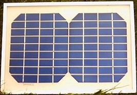
Obviously a solar panel does not generate its rated power 24 hours per day. Once you take into account nighttime, bad weather, and early mornings and evenings when the sun is low in the sky, there are not many hours of good generating time in the winter when this system is most important. For the UK you can expect an average of the equivalent of around 4 hours at the rated power per day in the spring and autumn, but in the winter this average can fall to less than 2 hours per day.
Therefore to get through the winter with solar only, you need a solar panel with a power rating of at least ten-twelve times that of the fan. With our example fan rated at 0.84 Watts, we need a solar panel rated at 10 Watts. Click here to buy a 10 Watt solar panel (10). Prices at the time of this article update (Jan 2014) start at around £20 delivered).
Depending on the exact geographical location of the greenhouse - further north in the northern hemisphere means less solar electricity generation - the quality of the battery used, and the direction the solar panel is facing, additional solar capacity may be necessary to make up for shortfalls and losses in the system. However a 10W solar panel with a fan rated at less than 1 Watt is a good starting point. A second solar panel can be added in parallel with the first if the solar generating potential of your location renders the 10 Watt panel insufficient.
If you were to choose a fan rated at 2 Watts for example, then a solar panel of 20 Watts would be required, and so on.
The Battery
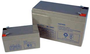
If a very small battery is used, a solar charge controller (12) will be necessary to prevent overcharging of the battery. In addition, there will be insufficient stored charge to cope with multiple overcast days. It is best to match the battery with the solar panel to ensure that there is enough stored charge capacity for the fan to be powered even if it is cloudy for a week. With a 10 Watt solar panel and a 0.84 Watt fan, something of the order of at least 15-20Ah would be perfect, and except in the summer months (when this frost preventing heatsink system is not going to be needed) a solar charge controller would not be necessary since overcharging would not be an issue with the battery constantly being slowly drained by the fan.
For our guide to selecting and purchasing suitable batteries for this and other solar applications, click here: 12V Deep Cycle Batteries for Solar (13).
Putting the Greenhouse Heatsink System Together
The final components of the system are a suitable fuse holder and fuse (14) (use a 2 Amp fuse for a 0.84W fan to protect against short circuits etc), and a switch (15) so that you can manually switch off the system if the battery is flat to give it a chance to recharge.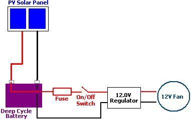
The fuse should be positioned as close as possible to the positive terminal of the battery to make it most effective. The on/off switch should be positioned between the battery and the voltage regulator (rather than between the regulator and the fan) so that no power is wasted when the system is switched off as voltage regulators use a little power even when there is no load connected to them.
Web Link References
(1) http://www.reuk.co.uk/Solar-Greenhouse-Heat-Sink.htm(2) http://www.reuk.co.uk/electric-circuit.htm
(3) http://www.reuk.co.uk/How-Do-PV-Solar-Panels-Work.htm
(4) http://www.awin1.com/cread.php?awinmid=1799&awinaffid=80045&clickref=&p=http%3A%2F%2Fwww.rapidonline.com%2Fsearchresults.aspx%3Fstyle%3D0%26kw%3D370927
(5) http://www.awin1.com/cread.php?awinmid=1799&awinaffid=80045&clickref=&p=http%3A%2F%2Fwww.rapidonline.com%2F
(6) http://www.reuk.co.uk/Lead-Acid-Batteries.htm
(7) http://www.reuk.co.uk/LM2940-12V-1A-Low-Dropout-Regulator.htm
(8) http://www.reuk.co.uk/buy-12-VOLT-REGULATOR.htm
(9) http://www.reuk.co.uk/REUK-Products-For-Sale.htm
(10) http://rover.ebay.com/rover/1/710-53481-19255-0/1?type=3&campid=5335956276&toolid=10001&customid=&ext=10+watt+solar+panel&satitle=10+watt+solar+panel
(11) http://www.reuk.co.uk/Deep-Cycle-Batteries-For-Sale.htm
(12) http://www.reuk.co.uk/Solar-Charge-Controller.htm
(13) http://www.reuk.co.uk/12-Volt-Deep-Cycle-Batteries-for-Solar.htm
(14) http://www.reuk.co.uk/buy-5A-FUSE.htm
(15) http://www.reuk.co.uk/buy-1.5A-TOGGLE-SWITCH.htm
Article from REUK.co.uk:
http://www.reuk.co.uk/Greenhouse-Heatsink-Connection-Diagram.htm
Published: 24th September 2014
© REUK 2026