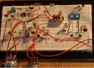
There is no need to solder anything, and the components can be moved around and the circuit modified thousands of times without damaging parts. When you have finished a prototype the components used can be removed and re-used another day on a different project, or having got the circuit working you can solder it together permanently on a PCB or matrix board.
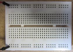
Originally breadboards were made from wood (hence the name) and pins were pushed through the bottom onto which wires and components could be soldered. The modern solderless breadboard is made from plastic with a grid of holes/sockets separated by a standard 0.1 inch pitchinto which wires and the legs of components can be inserted, and there is a wider gap along the centre line across which standard PCB mounting integrated circuit (IC) chips can be inserted.
The Connections in a Solderless Breadboard
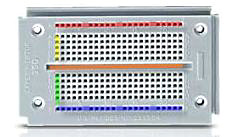
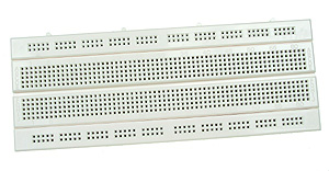
Inside a solderless breadboard are metal contacts which connect the holes/sockets together in a very specific and standard manner. On an example breadboard above those connections have been highlighted.
Across the top (red) is a long line of holes all connected to each other. This is for the positive power bus. You connect the positive of your power supply to this line and all holes along that line will have a positive connection which you can connect to and use in your circuit. Note that although this line is typically split into sections of 5 holes, those sections are all still connected to one another within the breadboard. If you have a breadboard with two lines instead of one then the two lines are isolated from each other.
Across the bottom (blue) is the long line of connected holes for the negative power bus. This works as per the positive bus mentioned above, but you connect the negative of your power supply to this line and then connect from the line to your circuit when you need a negative connection.
The rest of the holes on the breadboard are connected in vertical connected columns of five. The five holes highlighted in yellow are connected to each other, the five holes highlighted in green are connected to each other, but the line of yellow holes and the line of green holes are isolated from each other and from all the rest of the holes on the breadboard. The breadboard pictured above has 23 x 2 = 46 such columns of five connected holes.
The brown line across the centre shows the gap across which integrated circuits (and some other standard sized components) can be connected. Each pin of the IC then has its own column of four free holes to which other components and links can be inserted to make connections to those pins. There is no way to locate an IC on a breadboard other than across the centre line as pictured above without short circuiting opposing pins.
(If you look at the picture of the breadboard at the top of this page you will see that this larger version has its two power bus lines along the centre, and then the top and bottom halves both replicate the small breadboard discussed above, but with many more columns.)
Using a Breadboard – Example Circuit
In this simple example we will set up a circuit on a breadboard which will turn on an LED when a push-to-make button is pressed.
 1. Connect the positive and negative from the power supply to the positive and negative bus lines. |
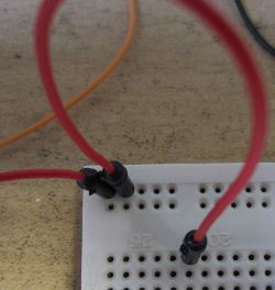 2. From the positive bus make a positive connection ready for the circuit. |
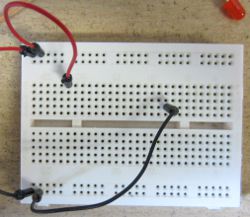 3. From the negative bus make a negative connection ready for the circuit. |
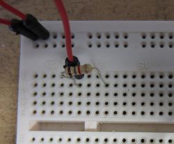 4. Insert one leg of a 1K8 resistor into the column with the line from the positive bus. |
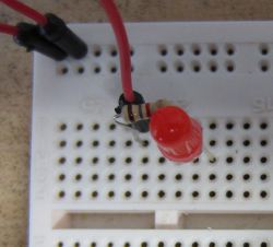 5. Insert the positive (long) leg of an LED in the same column as the other leg of the 1K8 resistor. |
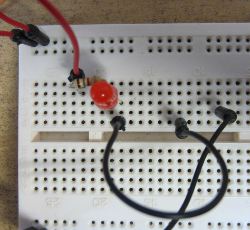 6. Connect a line to the negative (short) leg of the LED to bring it near to the line from the negative bus. |
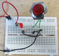 7. Connect the pushbutton leads to the columns to finish the circuit. |
|
…and now when the button is pressed, the circuit is completed and the LED lights up.
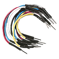
In order to electrically connect components together in that example and typically with breadboards, jumper links are used (as pictured below). While it is possible to make your own links from wire, it is best to use commercial jumper link since they are relatively cheap, flexible, sturdy, and available in a range of different lengths and colours – particularly useful when putting together complicated circuits.
Sometimes you will run out of jumper links of the right size or colour and have to come up with an alternative. For short links large office staples can be used – ideally wrapped in heatshrink tubing of different colours if you plan on using them multiple times.
Alternatively use a good single core insulated wire of around 0.6mm diameter (18 or 20 gauge). It is best not to use multi-stranded wire as although it is nice and flexible, there is a risk that a piece of a strand will break off and be left in the breadboard which can cause short circuits or block the hole. If you must use multi-stranded wire, twist the exposed ends very tightly and run a little bit of solder quickly along the length of the exposed wire to hold it together without forming any blobs of solder which will not fit into the holes of the breadboard.
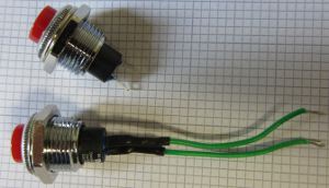
There are of course many components which cannot be connected directly to a breadboard due to the physical dimensions of their contacts – for example, the push-to-make button we used in the earlier example. To get around this, solder leads to the contacts of the component and plug those leads into the breadboard. If it is a component to which you cannot or do not want to solder leads, use crocodile leads to clip onto the contacts and clip the other ends of the leads to jumper links on the breadboard.
Buying Breadboards and Accessories
We have top quality great value 400-tie Protobloc prototyping breadboards for sale in the REUK Shop together with mixed bundles of 60 multi-coloured Protobloc jumper links of 100mm, 150mm, 200mm, and 250mm length – perfect to get you started on your first circuits.
A huge range of breadboards and jumper links are also available from eBay (typically despatched directly from China). Click here to see the latest listings for Breadboard and Jumper Links.