Low Voltage Disconnect for 0 to 5 Volt Range

We build and sell a wide range of low voltage disconnects for use with 12V and (less frequently) 24V battery systems to protect batteries from being overly discharged and therefore damaged.

Low voltage disconnect with oled display for very low voltages

Pictured above is a device for a slightly different application, but which is based around our REUK Programmable Low Voltage Disconnect with OLED Display.

This Arduino powered device is designed to interrupt a signal line (using an on board relay) when an input voltage is measured to be below a user set value expected to be in the range 0 to 5V. Since the input voltage could be too low to power the microcontroller and display etc, the board is powered by an external 12V supply with a common ground connection to the voltage to be measured.

The user can set the low voltage threshold below which the signal line will be cut (by the relay being de-energised), and then a higher voltage threshold above which the signal line connection will be restored (by the relay being re-energised). Timers are built in to this device so that 10 seconds of consistent low or high voltage is required for a change of state of the relay to occur so any brief input voltage spikes and dips, or interference do not have an effect.

If you need any kind of low voltage disconnect or automatic voltage monitoring device, please email neil@reuk.co.uk with details of your specific requirements.

Full Arduino Code for Poultry Egg Incubator with Humidity Sensor

We are frequently asked for the source code used on the Arduino-based products which we design and build. Unfortunately we cannot do that for commercial reasons. However, more than 80 percent of the requests we receive are for the code used in our poultry egg incubation controllers, with almost 100 percent of those requests coming from the developing world.

Therefore, as a one-off, we are releasing the full Arduino source code for our most popular (and easiest to build with commonly available components) device of this type, our Poultry Egg Incubator with Humidity Sensor.

egg incubator with humidity sensor, fan, heater, and humidifier

egg incubator controller status summary display

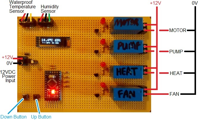
This device makes use of an always on motor which turns the eggs six full turns every 24 hours. Many of our other incubators have motors which have to be set up to run for a certain length of time a certain number of times per day, but the code for these is either specific to a particular motor or far more complicated (but of course more flexible) if the end-user of the incubator is to set these timings.

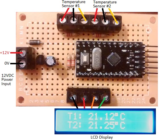
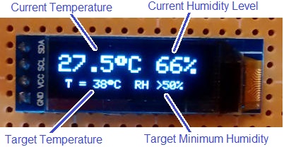
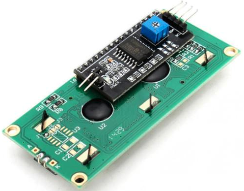
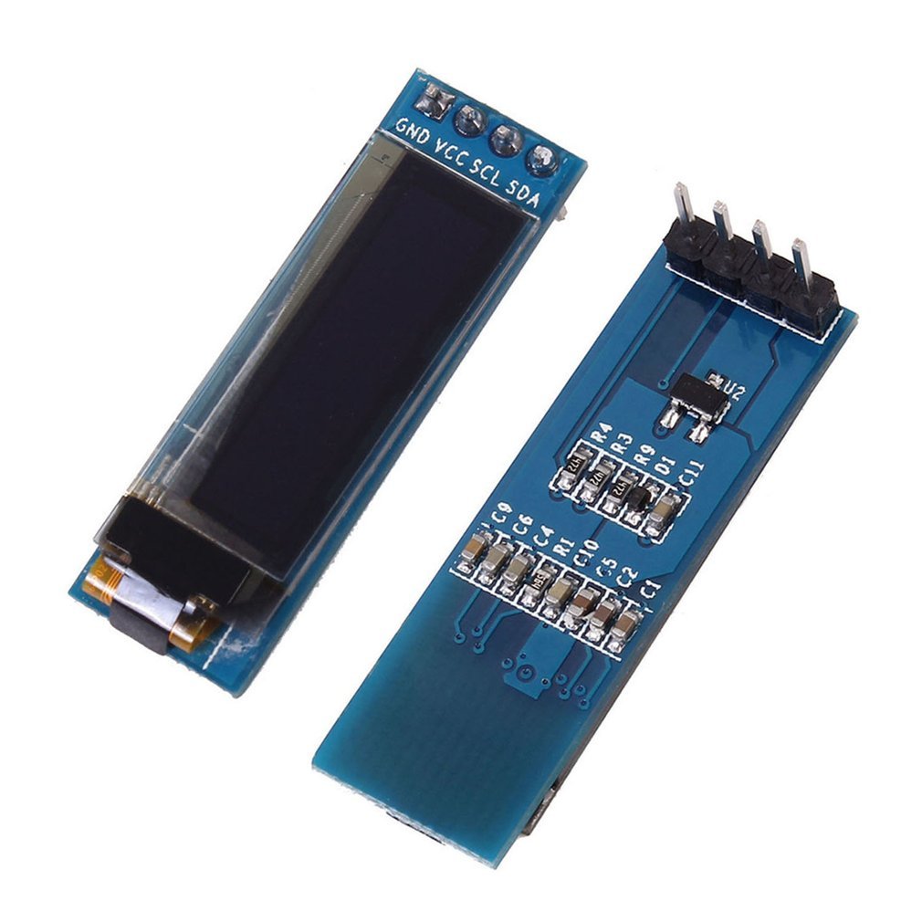
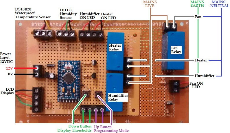
This device makes use of a DS18b20 digital temperature sensor, a 1602 LCD display module, a DHT11 humidity sensor, and is based around an Arduino Pro Mini, together with some relays, resistors, buttons, terminals, and other components available everywhere – easily salvaged from old and broken electronics even.

In time we will add a circuit diagram together with a suggested parts list, but the design is very flexible in terms of the components which can be used to put it together (with exception of the sensors and display for which the code provided is specific…and which together with an Arduino Pro Mini clone can be purchased for well under US$10 total including delivery.

Click here for details on how to connect and use a DHT11 Humidity Sensor with Arduino, and here for information on using DS18B20 sensors and 1602 LCD modules with Arduino.

Here is the full Arduino sketch (source code) for the egg incubator.

// (C) 2017-2020 REUK.CO.UK - Free for non-commercial use.
// Egg incubation temperature and humidity controller with display.
// Connection to an always on motor - e.g. 6 rotations per day.
// Fan for cooling, heater for heating, humidifier to humidify.

// For the temperature sensor.
#include <OneWire.h>
#include <DallasTemperature.h>
#define ONE_WIRE_BUS 3

// For the non-volatile storage.
#include <EEPROM.h> //EEPROM.write(addr, val); val = EEPROM.read(address);

// For the DHT11 humidity sensor.
#include <dht.h>
dht DHT;
#define DHT11_PIN 10

//for the LCD
#include <Wire.h>
#include <LCD.h>
#include <LiquidCrystal_I2C.h>
#define I2C_ADDR 0x27 // This i2c address depends on the display.
#define BACKLIGHT_PIN 3
#define En_pin 2
#define Rw_pin 1
#define Rs_pin 0
#define D4_pin 4
#define D5_pin 5
#define D6_pin 6
#define D7_pin 7
LiquidCrystal_I2C lcd(I2C_ADDR,En_pin,Rw_pin,Rs_pin,D4_pin,D5_pin,D6_pin,D7_pin);

// Setup a oneWire instance to communicate with the OneWire 
// device (Dallas temperature IC)
OneWire oneWire(ONE_WIRE_BUS);

// Pass our oneWire reference to Dallas Temperature. 
DallasTemperature sensor1(&oneWire);

// Set up the input and output pins used on the Arduino.
const int button1 = 2;
const int button2 = 8;
const int heater = 9;
const int fan = 4;
const int humidifier = 5;

// Define variables to store the humidity and 
// temperature readings froms sensors.
float sensorOneTemperature;
float humidity;

// Define variables for the upper and lower 
// thresholds (read in from EEPROM).
float heaterOnThreshold;
float heaterOffThreshold;
float fanOnThreshold;
float fanOffThreshold;
float humidifierOnThreshold;
float humidifierOffThreshold;

// Define the memory locations of the thresholds in EEPROM.
int heaterOnEEPROM = 100;
int heaterOffEEPROM = 120;
int fanOnEEPROM = 140;
int fanOffEEPROM = 160;
int humidifierOnEEPROM = 180;
int humidifierOffEEPROM = 200;

// Set some default values for the thresholds.
const float heaterOnDefault = 37.0;
const float heaterOffDefault = 39.0;
const float fanOnDefault = 40.0;
const float fanOffDefault = 37.0;
const float humidifierOnDefault = 45.0;
const float humidifierOffDefault = 70.0;

// Define variables to keep track of the status of 
// the system (0=off,1=on)
int heaterStatus;
int fanStatus;
int humidifierStatus;

void setup(void)
{
 // Start up the temperature sensor library.
 sensor1.begin();
 // Set the temperature measurement resolution to 
 // 12 bit ADC (0.0625°C resolution)
 sensor1.setResolution(12);

 // Read in the threshold values from EEPROM.
 heaterOnThreshold = EEPROM_readFloat(heaterOnEEPROM);
 heaterOffThreshold = EEPROM_readFloat(heaterOffEEPROM);
 fanOnThreshold = EEPROM_readFloat(fanOnEEPROM);
 fanOffThreshold = EEPROM_readFloat(fanOffEEPROM);
 humidifierOnThreshold = EEPROM_readFloat(humidifierOnEEPROM);
 humidifierOffThreshold = EEPROM_readFloat(humidifierOffEEPROM);

 // Make sure that we at least have read in values, or read in defaults.
 if(isnan(heaterOnThreshold)) heaterOnThreshold = heaterOnDefault;
 if(isnan(heaterOffThreshold)) heaterOffThreshold = heaterOffDefault;
 if(isnan(fanOnThreshold)) fanOnThreshold = fanOnDefault;
 if(isnan(fanOffThreshold)) fanOffThreshold = fanOffDefault;
 if(isnan(humidifierOnThreshold)) humidifierOnThreshold = humidifierOnDefault;
 if(isnan(humidifierOffThreshold)) humidifierOffThreshold = humidifierOffDefault;
 
 // Set up the inputs and outputs on the Arduino IO
 pinMode(button1, INPUT);
 digitalWrite(button1, HIGH); //turn on the pull up resistor
 pinMode(button2, INPUT);
 digitalWrite(button2, HIGH); //turn on the pull up resistor
 pinMode(heater, OUTPUT);
 digitalWrite(heater, LOW);
 pinMode(fan, OUTPUT);
 digitalWrite(fan, LOW);
 pinMode(humidifier, OUTPUT);
 digitalWrite(humidifier, LOW);
 
 // Need to keep track of the status of the heater, fan, and humidifier
 // so we know whether they are on or off.
 heaterStatus = 0; // Start with the heating element off (=0)
 fanStatus = 0; // Start with the fan off
 humidifierStatus = 0; // Start with humidifier turned off
 
 // Set up the LCD
 lcd.begin (16,2);
 // Switch on the backlight.
 lcd.setBacklightPin(BACKLIGHT_PIN,POSITIVE);
 lcd.setBacklight(HIGH);
 // Clear the display.
 lcd.clear();
 delay(200);
}

void loop(void)
{ 
 // Read in the temperature and humidity and display across 
 // the top line of the display.
 readInAndDisplayTemperature();
 readInAndDisplayHumidity();
 // Display the current system status on the bottom line of the display.
 displaySystemStatus();

 // If heater is currently off, and temperature is low, turn on the heater.
 if(heaterStatus == 0 and sensorOneTemperature < heaterOnThreshold){
 digitalWrite(heater, HIGH);
 heaterStatus = 1;
 }
 
 // If heater is currently on, and temperature is high, turn off the heater.
 if(heaterStatus == 1 and sensorOneTemperature > heaterOffThreshold){
 digitalWrite(heater, LOW);
 heaterStatus = 0;
 }

 // If fan is currently off, and temperature is high, turn on the fan.
 if(fanStatus == 0 and sensorOneTemperature > fanOnThreshold){
 digitalWrite(fan, HIGH);
 fanStatus = 1;
 }
 
 // If fan is currently on, and temperature is low, turn off the fan.
 if(fanStatus == 1 and sensorOneTemperature < fanOffThreshold){
 digitalWrite(fan, LOW);
 fanStatus = 0;
 }

 // If humidifier is currently off, and humidity is low, turn on the humidifier.
 if(humidifierStatus == 0 and humidity < humidifierOnThreshold){
 digitalWrite(humidifier, HIGH);
 humidifierStatus = 1;
 }
 
 // If humidifier is currently on, and humidity is high, turn off the humidifier.
 if(humidifierStatus == 1 and humidity > humidifierOffThreshold){
 digitalWrite(humidifier, LOW);
 humidifierStatus = 0;
 }

 // Press and hold button1 for half a second to briefly show 
 // the thresholds currently set.
 if(digitalRead(button1)==LOW){
 int i;
 for(i = 0; i < 5; i++){
 delay(100);
 if(digitalRead(button1) == HIGH) i = 20;
 }
 // If button was held for at least 1/2 second, display thresholds...
 if(i < 11){
 displayThresholds();
 }
 }
 
 // Press and hold button2 for half a second to enter programming mode.
 if(digitalRead(button2)==LOW){
 int i;
 for(i = 0; i < 5; i++){
 delay(100);
 if(digitalRead(button2) == HIGH) i = 20;
 }
 // If button was held for at least 1/2 second we go into programming mode.
 if(i < 11){
 programmingMode();
 }
 }
}

void programmingMode(){
 // We arrive in here with the button2 currently being pressed 
 // and entering programming mode.
 lcd.clear();
 lcd.setCursor(0,0);
 // Make sure that the user has released the programming button
 while (digitalRead(button1) == LOW) {
 delay(100);
 }
 lcd.print("PROGRAMMING MODE");

 // Wait for button2 to be released.
 do{
 delay(50);
 }while(digitalRead(button2) == LOW);

 // FIRST of all we are going to programme in the new value 
 // for heaterOnThreshold
 lcd.setCursor(0,0);
 lcd.print("set Heater ON T ");
 displayANumberDuringProgramming(heaterOnThreshold);
 for(int i = 0; i < 50; i++){
 delay(100);
 if(digitalRead(button1) == LOW){ // go down
 heaterOnThreshold = heaterOnThreshold - 0.2;
 displayANumberDuringProgramming(heaterOnThreshold);
 i = 0; 
 waitForButton1Release();
 }
 if(digitalRead(button2) == LOW){ // go up
 heaterOnThreshold = heaterOnThreshold + 0.2;
 displayANumberDuringProgramming(heaterOnThreshold);
 i = 0;
 waitForButton2Release();
 }
 }
 EEPROM_writeFloat(heaterOnEEPROM, heaterOnThreshold);

 // SECOND we set the new value for heaterOffThreshold.
 lcd.setCursor(0,0);
 lcd.print("set Heater OFF T ");
 displayANumberDuringProgramming(heaterOffThreshold);
 for(int i = 0; i < 50; i++){
 delay(100);
 if(digitalRead(button1) == LOW){ // go down
 heaterOffThreshold = heaterOffThreshold - 0.2;
 displayANumberDuringProgramming(heaterOffThreshold);
 i = 0; 
 waitForButton1Release();
 }
 if(digitalRead(button2) == LOW){ // go up
 heaterOffThreshold = heaterOffThreshold + 0.2;
 displayANumberDuringProgramming(heaterOffThreshold);
 i = 0;
 waitForButton2Release();
 }
 }
 EEPROM_writeFloat(heaterOffEEPROM, heaterOffThreshold);

 // THIRD we are going to programme in the new value 
 // for fanOnThreshold.
 lcd.setCursor(0,0);
 lcd.print("set fan ON T ");
 displayANumberDuringProgramming(fanOnThreshold);
 for(int i = 0; i < 50; i++){
 delay(100);
 if(digitalRead(button1) == LOW){ // go down
 fanOnThreshold = fanOnThreshold - 0.2;
 displayANumberDuringProgramming(fanOnThreshold);
 i = 0; 
 waitForButton1Release();
 }
 if(digitalRead(button2) == LOW){ // go up
 fanOnThreshold = fanOnThreshold + 0.2;
 displayANumberDuringProgramming(fanOnThreshold);
 i = 0;
 waitForButton2Release();
 }
 }
 EEPROM_writeFloat(fanOnEEPROM, fanOnThreshold);

 // FOURTH we are going to programme in the new value
 // for fanOnThreshold.
 lcd.setCursor(0,0);
 lcd.print("set fan OFF T ");
 displayANumberDuringProgramming(fanOffThreshold);
 for(int i = 0; i < 50; i++){
 delay(100);
 if(digitalRead(button1) == LOW){ // go down
 fanOffThreshold = fanOffThreshold - 0.2;
 displayANumberDuringProgramming(fanOffThreshold);
 i = 0; 
 waitForButton1Release();
 }
 if(digitalRead(button2) == LOW){ // go up
 fanOffThreshold = fanOffThreshold + 0.2;
 displayANumberDuringProgramming(fanOffThreshold);
 i = 0;
 waitForButton2Release();
 }
 }
 EEPROM_writeFloat(fanOffEEPROM, fanOffThreshold);

 // FIFTH we are going to programme in the new value
 // for humidifierOnThreshold
 lcd.setCursor(0,0);
 lcd.print("set Humidi ON % ");
 displayANumberDuringProgramming(humidifierOnThreshold);
 for(int i = 0; i < 50; i++){
 delay(100);
 if(digitalRead(button1) == LOW){ // go down
 humidifierOnThreshold = humidifierOnThreshold - 2;
 displayANumberDuringProgramming(humidifierOnThreshold);
 i = 0; 
 waitForButton1Release();
 }
 if(digitalRead(button2) == LOW){ // go up
 humidifierOnThreshold = humidifierOnThreshold + 2;
 displayANumberDuringProgramming(humidifierOnThreshold);
 i = 0;
 waitForButton2Release();
 }
 }
 EEPROM_writeFloat(humidifierOnEEPROM, humidifierOnThreshold);

 // SIXTH we are going to programme in the new value
 // for humidifierOffThreshold
 lcd.setCursor(0,0);
 lcd.print("set Humidi OFF % ");
 displayANumberDuringProgramming(humidifierOffThreshold);
 for(int i = 0; i < 50; i++){
 delay(100);
 if(digitalRead(button1) == LOW){ // go down
 humidifierOffThreshold = humidifierOffThreshold - 2;
 displayANumberDuringProgramming(humidifierOffThreshold);
 i = 0; 
 waitForButton1Release();
 }
 if(digitalRead(button2) == LOW){ // go up
 humidifierOffThreshold = humidifierOffThreshold + 2;
 displayANumberDuringProgramming(humidifierOffThreshold);
 i = 0;
 waitForButton2Release();
 }
 }
 EEPROM_writeFloat(humidifierOffEEPROM, humidifierOffThreshold);
}

void waitForButton1Release(){
 do{
 delay(50);
 }while(digitalRead(button1) == LOW);
}

void waitForButton2Release(){
 do{
 delay(50);
 }while(digitalRead(button2) == LOW);
}

void displayANumberDuringProgramming(float theNumber){
 lcd.setCursor(0,1);
 lcd.print(" ");
 lcd.print(theNumber,1);
 lcd.print(" ");
}

void readInAndDisplayTemperature(){
 readTemperatureSensor();
 displayTemperature(); 
}
void readTemperatureSensor(){
 sensor1.requestTemperatures();
 sensorOneTemperature = sensor1.getTempCByIndex(0); 
}
void displayTemperature(){
 // Need to deal with below zero temperatures and also 
 // with above 100 degree temperatures. Adjust number of
 // decimal places to result in similar number of overall 
 // digits used.
 int dp; //number of decimal places to show
 
 // Show the temperature on the screen
 lcd.setCursor(0,0);
 dp = 2; //by default
 if (sensorOneTemperature > 99.9) dp = 0; 
 if (sensorOneTemperature < 0) dp = 0;
 lcd.print("T=");
 lcd.print(sensorOneTemperature,dp);
 lcd.print((char)223);
 lcd.print("C");
 lcd.print(" ");
}

void readInAndDisplayHumidity(){
 readInHumidity();
 displayHumidity(); 
}

void readInHumidity(){
 // Read in the humidity from the sensor and set it 
 // to the global variable 'humidity'.
 int chk = DHT.read11(DHT11_PIN);
 humidity = DHT.humidity;
}

void displayHumidity(){
 // Note - always call this function immediately
 // after displaying the temperature.
 lcd.print("H=");
 lcd.print(humidity,0);
 lcd.print("% ");
}

void displaySystemStatus(){
 lcd.setCursor(0,1);
 // We need to display the status of the heater, fan,
 // and humidifier which can be ON or OFF. If status is
 // ON, fill in character in front of device name.
 if(heaterStatus == 1) 
 lcd.write(255);
 else lcd.print(" ");
 lcd.print("Heat ");
 if(fanStatus == 1)
 lcd.write(255);
 else lcd.print(" ");
 lcd.print("Fan ");
 if(humidifierStatus == 1)
 lcd.write(255);
 else lcd.print(" ");
 lcd.print("Hum ");
}

void displayThresholds(){
 // Arrive here with button1 currently depressed.
 // Show the six programmed thresholds on the screen
 // for three seconds each.

 // First of all show the heater thresholds.
 lcd.clear();
 lcd.print("Heater ");
 lcd.setCursor(0,1);
 lcd.print(heaterOnThreshold,1);
 lcd.print((char)223);
 lcd.print("C to ");
 lcd.print(heaterOffThreshold,1);
 lcd.print((char)223);
 lcd.print("C ");
 delay(3000);

 // Now show the fan thresholds.
 lcd.setCursor(0,0);
 lcd.print("Fan ");
 lcd.setCursor(0,1);
 lcd.print(fanOnThreshold,1);
 lcd.print((char)223);
 lcd.print("C to ");
 lcd.print(fanOffThreshold,1);
 lcd.print((char)223);
 lcd.print("C ");
 delay(3000);

 // Now show the humidifier thresholds.
 lcd.setCursor(0,0);
 lcd.print("Humidifier ");
 lcd.setCursor(0,1);
 lcd.print(humidifierOnThreshold,0);
 lcd.print("% to ");
 lcd.print(humidifierOffThreshold,0);
 lcd.print("% ");
 delay(3000);
}

//---------------------------------------------------------
// Utility functions to write float values to EEPROM and to 
// read them back in again.
void EEPROM_writeFloat(int ee, float value)
{
 byte* p = (byte*)(void*)&value;
 for (int i = 0; i < sizeof(value); i++)
 EEPROM.write(ee++, *p++);
}

float EEPROM_readFloat(int ee)
{
 float value = 0;
 byte* p = (byte*)(void*)&value;
 for (int i = 0; i < sizeof(value); i++)
 *p++ = EEPROM.read(ee++);
 return value;
}

Converting Digital Watch into a Timer Stopwatch for Projects

Pictured below are the inner workings of a cheap digital watch which has been modified to enable remote operation of the buttons so it can be used for automatic stopwatch timing.

Modified digital watch used as stopwatch with remote buttons or relay control

This particular watch had a broken backlight and broken strap, but it had always kept very good time. Therefore it was a perfect candidate to be re-purposed.

The watch had rubber button tops integrated into the watch case. When the workings are removed from the case, the buttons themselves are exposed. They comprise a thin strip of metal separated from a metal pad on the watch PCB. When the rubber button top is pressed down, the metal strip makes contact with the metal pad making an electrical connection.

Inside look at a digital watch button

All of the metal strips are connected to the watch battery ground, so the watch detects button presses by waiting for 0V to appear on one of the metal pads (which are electrically connected to the microcontroller inside the watch).

We soldered wires to the three metal pads of the buttons we wanted to control, and a ground wire to one of the commonly connected metal strips. Shorting the end of this ground wire to the end of any of the other wires causes the relevant button operation to take place.

relay board to control a stopwatch for timing arduino projectsWe next made the above pictured board. We put three tactile switches on the board and wired them up so that when pressed, they would short a mode button input to ground. These tact switches make it much easier to interact with the wired-up watch manually.

Then we added a small 5V coil relay and connected its NO and COM pins to the Start/Stop button connection and to ground for the watch. When the relay is energised (closed) it will simulate the Start/Stop button of the watch being held down.

The final component is an Arduino Pro Mini in a socket. This board will be used to calibrate the internal clocks of Arduino Pro Mini clones as their crystals are not accurate enough for some of the projects we build.

(Note that we are powering this board with 12VDC for convenience as that is the voltage we use for all of our testing rigs with a bench power supply, but for a one off it would have been 5VDC powered – 4 AA cells for example.)

Controlling the Stopwatch via Arduino and Calibrating the Arduino’s Internal Clock

 digitalWrite(relay, HIGH);
 delay(50);
 digitalWrite(relay, LOW);

The Arduino code above is used to briefly energise the relay which starts and stops the stopwatch. We used a 50 millisecond delay so that the relay has time to energise (physically close its internal contacts) and button presses of under 20 milliseconds were ignored by this watch. When someone presses a button, they typically keep it held down for from 30-70 milliseconds, so we replicated that.

To roughly measure how long is 10 seconds for the Arduino, we used the following code:

digitalWrite(relay, HIGH);
delay(50);
digitalWrite(relay, LOW);

delay(10000);

digitalWrite(relay, HIGH);
delay(50);
digitalWrite(relay, LOW);

It starts the stopwatch, waits 10,000 milliseconds, and then stops the stopwatch. If the Arduino is accurate, the stopwatch will stop with 10.00 seconds displayed. In a few quick runs we got 10.03, 10.07, 10.06, 10.06, 10.03, 10.03, and 10.06 seconds. This seems to show that this particular Arduino Pro Mini was running a little slow (it could also be that it takes longer for the relay to energise than de-energise which could be significant when only timing 10 seconds).

The delay() function is not accurate in general since we do not know how long the loop execution time is. Instead for accurate time testing we use millis().
Replacing delay(10000); with the following:

unsigned long startTime = millis();
do{
  delay(1);
} while (startTime + 10000> millis());

we got 10.00, 10.00, 10.00, 10.00, 10.00, 10.00, and 10.00 seconds on the stopclock in initial testing.

For calibration we test for a minimum of 8 hours, but sometimes 12 or 24 hours. The longer the test, the greater the accuracy of the results and therefore the better we can calibrate the Arduino’s internal clock.

There are 28800000 milliseconds in 8 hours for example. So we’d modify the code above to have while(startTime + 28800000 > millis()); . After 8 hours, the stopwatch will show a time. We found that that this Arduino Pro Mini was running 4 seconds slow….so after 8 hours the clock showed 8h 00m 04s.
There are 28,000 seconds in 8 hours, so the error in the Arduino clock is
1 – 28,000/28004 = 0.0001428 = 0.01428%.
We can save this percentage error in memory on this Arduino Pro Mini and take it into account when using it in timing applications. If we want to use this Pro Mini to time 5 hours accurately, we’d run the timer for 5 hours minus 0.01428% of 5 hours.

PPC 1500 Target Shooting Timer

PPC 1500 target shooting timer controller relay

Pictured above is a timer we recently built to control the start and finish horn for PPC 1500 shooting competitions.

In competition a button is pressed followed by a 3 second delay. Then the timer begins counting down from 8 secs,12 secs, 20 secs, 35 secs, 90 secs, or 165 secs with a horn sounding for 0.75 seconds as the timer starts, and again for 0.5 seconds after the timer has finished.

The user can select the timing option using the on board button, an external button, or using a remote control switch.

The on board display shows the current setting while the timer is not running, and then shows the countdown ticking down while it is running. The start button can also be used to stop the timer when it is running to reset the system.

A second button enables the user to sound the horn at any time while the button is being pressed.

If you need any time of timer controller, please email neil@reuk.co.uk with details of your specific requirements.

Arduino Two Channel Thermometer with Display (Full Code)

Pictured below is a two-channel thermometer we recently built for a customer. This device takes inputs from two ds18b20 temperature sensors and displays their measured temperatures on a 1602 LCD display module. The thermometer is built around an Arduino Pro Mini.

Arduino double thermometer with lcd display - full code provided

Below is the full Arduino sketch (code) for our device.

See this guide to Connecting an I2C Display to Arduino for the LCD connections. We have added the necessary 3k3 pull up resistors between pin A4 and 5V, and pin A5 and 5V – click here to read about I2C Pull Up Resistors. We have also used an external 5V regulator rather than relying on the 5V regulator built into the Arduino Pro Mini, and added reverse polarity protection on the input with a 1N4001 diode.

// © reuk.co.uk - 2018
// Double Thermometer with Display.

// For the DS18B20 temperature sensors.
#include <OneWire.h> // (https://github.com/PaulStoffregen/OneWire)
#include <DallasTemperature.h> // (https://github.com/milesburton/Arduino-Temperature-Control-Library)

// Data wires are plugged into pins 2 and 3 on the arduino.
#define ONE_WIRE_BUS 2
#define SECOND_BUS 3

// For the 1602 LCD module.
#include <Wire.h>
#include <LCD.h>
#include <LiquidCrystal_I2C.h>
#define I2C_ADDR 0x27 // Note that some modules have address 0x3F

#define BACKLIGHT_PIN 3
#define En_pin 2
#define Rw_pin 1
#define Rs_pin 0
#define D4_pin 4
#define D5_pin 5
#define D6_pin 6
#define D7_pin 7
LiquidCrystal_I2C lcd(I2C_ADDR,En_pin,Rw_pin,Rs_pin,D4_pin,D5_pin,D6_pin,D7_pin);

// Setup a oneWire instances to communicate with OneWire devices.
OneWire oneWire(ONE_WIRE_BUS);
OneWire secondWire(SECOND_BUS);

// Pass our oneWire reference to Dallas Temperature.
DallasTemperature sensor1(&oneWire);
DallasTemperature sensor2(&secondWire);

float sensorOneTemperature = 0.0;
float sensorTwoTemperature = 0.0;

void setup(void)
{
 // Start up the temperature sensor library.
 sensor1.begin();
 sensor2.begin();
 
 // Set the temperature sensor resolutions to 11 bit
 // ADC (12 bit is much slower but higher resolution).
 sensor1.setResolution(11);
 sensor2.setResolution(11);
 
 // Initialise the LCD.
 lcd.begin (16,2); // For a 16x2 character LCD
 // Switch on the LCD backlight.
 lcd.setBacklightPin(BACKLIGHT_PIN,POSITIVE);
 lcd.setBacklight(HIGH);
 // Clear the LCD screen.
 lcd.clear();
}

void loop(void)
{ 
 // Read in the temperatures of the two sensors.
 sensor1.requestTemperatures(); // Read temperature of sensor1
 sensorOneTemperature = sensor1.getTempCByIndex(0);
 sensor2.requestTemperatures(); // Read temperature of sensor2
 sensorTwoTemperature = sensor2.getTempCByIndex(0);

 // Display the temperatures of the sensors on the LCD.
 displayTemperatures();
}

void displayTemperatures(){
 // Display sensor1's temperature.
 lcd.setCursor(0,0);
 lcd.print(" T1: ");
 lcd.print(sensorOneTemperature,2);
 lcd.print((char)223);
 lcd.print("C ");
 
 // Display sensor2's temperature.
 lcd.setCursor(0,1);
 lcd.print(" T2: ");
 lcd.print(sensorTwoTemperature,2);
 lcd.print((char)223);
 lcd.print("C ");
}

If you need any kind of bespoke thermometer or thermostat, please email neil@reuk.co.uk with details of your specific requirements.

Formula 1 Race Starting Lighting Timer

formula 1 racing timerPictured above is a timer we recently built for a customer which will be used in a Formula 1 style race start lighting gantry. This gantry will be fitted at the top of a slope with toy cars held by a small gate latched up by a small solenoid with a spring loaded core. When the race is to start, the solenoid is energised which drops the gate allowing the cars to roll down the slope in their race.

In the photograph, five red LEDs are temporarily attached to the timer board for testing, but these will be mounted into the gantry across the track when it is finished.

When the user presses the button, the LEDs follow the standard F1 race start sequence – each red LED turns on in sequence with a one second interval. As each LED turns on, an on board piezo buzzer briefly pips. Then, when all five LEDs are illuminated, there is a random time interval of between 1 and 3 seconds before all the LEDs are turned off.

formula 1 race starting gantryThe lights turning off indicates that the race is to start. The buzzer sounds for 1 second, while the on board relay energises for 1 second to energise the solenoid and start the race.

Another Race Starting Timer

Pictured below is another similar race starting timer we made which controls three powerful lights via external relays.

3-light-formula-one-start-timerWhen the start button is pressed, there is a five second delay, then the three lights turn on one by one at one second intervals. After a random 0.5 to 4-5 second delay, the lights all turn back off.

If you need any kind of bespoke timer or controller, please email neil@reuk.co.uk with details of your requirements.

2x12V 24V Battery Bank Low Voltage Disconnect

24V battery bank low voltage disconnect LVD with dual battery measurementPictured above is a low voltage disconnect (LVD) we recently made for use with a 24V battery bank comprising two 12V batteries. These two batteries do not equalise well (i.e. they do not hold the exact same charge or show the same voltage), and so this low voltage disconnect has to look at both batteries independently and take actions based upon the measurements of the weakest battery.

This device is based around our OLED display 12V LVD with some major modifications. The batteries are connected in series to make a 24V bank. The device measures the voltage of the whole battery bank and also measures the voltage of the first 12V battery. The second 12V battery voltage is then calculated by subtracting the first 12V battery voltage from the 24V battery bank voltage.

OLED display on 24V battery bank LVDThe OLED display on the low voltage disconnect shows the two battery voltages which make up the bank, the status of the LVD, and the voltage threshold (user programmable) at which the status of the LVD will next change (turn off the output if it is on, turn it on if it is off) depending on the charge level of the two batteries in the bank.

If the voltage of either battery in the battery bank falls below the low voltage threshold set by the user, the output will be turned off cutting the power to any devices being powered by the battery bank. When both of the batteries in the bank then reach a voltage in excess of the high voltage threshold set by the user, the output is restored reconnecting power to the devices powered by the battery bank.

If you need any kind of low voltage disconnect, please take a look at our range of LVD products, and email neil@reuk.co.uk if you have any special requirements.

Dual Pulse Spot Welder Timer Controller

Pictured below is our popular 12VDC dual pulse spot welder timer controller which we designed, build, and sell.dual pulse spot welder controller

Spot welding (resistance spot welding – RSW) is used to join metal surfaces by passing a large electric current through them. Because of the heat generated by the resistance to the electric current, the contacting metals melt together forming a weld at the spot through which the current is passing.

In order to get good clean reliable welds and not to burn holes through the metal, it is essential that the pulse of electric current is of a suitable duration which depends on the types and thicknesses of the metals to be welded as well as many other factors. Therefore an accurate timer controller is required for consistent welds.

For the best spot welds, a dual pulse controller is used in which the electric current flows for a time (pre-weld), then there is a brief pause, and then electric current flows again (welding). The first pulse clears away any plating or surface oxidation, and then the second pulse welds the now clean base materials together. Using a dual pulse welder also reduces spitting.

REUK Dual Pulse Spot Welder Controller

Our controller offers two modes of operation: single pulse mode and dual/double pulse mode. Pictured below is a view of the built in OLED display when in dual pulse mode.

dual pulse spot welder display

The user can set the durations of Pulse 1, the pause time, and Pulse 2 in 0.01 second steps between 0.01 and 1.99 seconds.

single pulse operation of spot welder

In single pulse mode, the duration of just one pulse has to be set by the user. (A future update of this device will probably include up to 10 user-programmable presets for increased convenience.)

setting spot welder pulse duration

On board buttons are provided for toggling between the single and double pulse modes, entering programming mode to set the timings, and making a spot weld with the displayed settings. Screw in terminals are provided so that external buttons can be connected – for example a foot pedal to make a weld with your hands free.

This version of the welder controller is fitted with a 10A relay which can be used to power a < 5A rated solenoid which in turn switches the welder.

Buy a Welder Timer Controller for Your Relay

For any type of welder timer controller, please email neil@reuk.co.uk with details of any special requirements. Our controller as described above is available at £21.95 plus postage.

If you require a timer which will be switching more than 10 Amps of current for your welding setup, then we also make the alternative devices pictured below which have a 1 Amp 12V output for connection to your own solid state relay (SSR) or mechanical relay. These are available for £19.95 plus postage – no relay included. Click here for a source of solid state relays.

reuk dual pulse welder timer controller for solid state relay

dual pulse welder timer with solid state relay (ssr)

If you require a bespoke device which pulses the welder with very brief times and higher time resolution – e.g. 0.001s – 1.999s instead of 0.01-1.99s – we can modify the above photographed timer controller…but only for use with a solid state relay (since SSRs can switch in 1ms (0.001s) rather than the 10’s of milliseconds it can potentially take a mechanical relay to switch). Contact us with details of your specific requirements for a quotation.

Dual Pulse Spot Welder Timer Instructions

There are two buttons on the controller. If you press the ‘down’ button, you can toggle between single pulse and dual/double pulse operation. The display will change to show which mode you are in: SINGLE or DBL (double) as well as showing the durations currently programmed into the device.

If you press and hold the down button for more than one second, the display will show SET TIMERS. If you are in single pulse mode, you can now set the single pulse duration. If you are in double pulse mode you can now set the durations of pulse 1, the pause time, and pulse 2. The top line of the display will show what is currently being programmed (Time 1, Pause Time, or Time 2), and the bottom line will show the current value. Use the up and down buttons to increase or decrease the displayed value (within the range 0.01s to 0.99s). Five seconds after you last touched a button, the top line of the display will show -SAVED- and the value will be saved in long term memory (still available the next time you power on the controller). If you are in double pulse mode, you will now be asked to set the pause time and the duration of the second pulse in exactly the same way that Time 1 was set. (When using the up and down buttons to increase or decrease a time value, you can press and hold the button to move faster through the numbers.)

If you press the up button, the controller will run. The relay will close for the duration of Time 1 and then open again. If you are in double pulse mode, it will then remain open for the duration of Pause Time and then close for the duration of Time 2.

In addition to the buttons on the controller board itself, screw in terminals are provided to which you can connect external buttons of your choosing – e.g. a foot pedal operated button, or a larger hand operated button etc for your own convenience.

Poultry Egg Incubator with On Board Display and Humidity Maintenance

We have made many poultry egg incubators and timers over the last few years – devices which monitor and maintain temperature and humidity and also turn the eggs at regular intervals. Below is an image of one such incubator controller which we were recently commissioned to build which is a bit different from those.

poultry egg incubator controller

The motor is set to turn for three seconds five times per day to rotate the eggs. This is standard.

The heating element used for this incubator is a bit oversized, so we have to be careful not to overheat the eggs when it is used. When the temperature is measured to be 0.5C or more below a user set target temperature, the heater is turned on. Then, when the target temperature is reached, the heater is turned off. Because the element remains hot after being turned off, the incubator will continue to heat up to a little above target temperature while the element cools down. Therefore, there is also a fan which turns on just in case the temperature exceeds the target by 1.5C or more to cool things down long before the eggs overheat.

display for poultry egg incubation controller

Humidity management is also achieved rather differently than usual. In all previous incubators we have made which have included humidity sensing, a commercial humidifier has been switched on/off to maintain appropriate humidity levels. For this controller, when humidity is measured to be below a user set target minimum level, a pump is turned on for five second which adds water to a container in the incubator. The rapid evaporation of this water in the warmth of the incubator increases the humidity level back above the minimum rapidly. In order to prevent flooding or raising the humidity level excessively, the controller will run the pump at most once every ten minutes.

This entire system is powered by a solar charged 12V battery bank.

If you need any type of incubator (or humidor), please email neil@reuk.co.uk with details of your requirements.

Testing 128×32 OLED IIC Display with Arduino

Many of the products we sell make use of 16×2 character LCD displays. These displays coupled with an Hitachi HD44780 LCD control module enable an Arduino or Raspberry Pi to operate the display very simply with just two data connections and two power connections required.

16x2 LCD display with module for use with Arduino and Raspberry Pi

However, these displays are physically quite large being 80 x 36mm, and while they are well suited to panel mounting, they cannot really be attached to the circuit board that is driving it without creating a device with large dimensions.

We have recently being looking at alternatives to these displays looking for something physically smaller, easily circuit board mountable, lower power consumption, and improved contrast. After much testing, we have chosen the OLED display pictured below.128x32 i2c arduino displayThese displays are far smaller having an active screen area of just 22.38 x 5.58mm. They require no backlight as each of the 128×32 pixels self-illuminates thanks to OLED technology. The maximum power consumption of one of these displays is 0.08W with every pixel illuminated – therefore less when showing text or when nothing is being displayed. In all ways these displays are an improvement on the 16×2 character LCDs.

OLED display used with arduinoThese OLED displays have much better contrast than LCDs, there is more space available to display information since more characters can be displayed, and there are much better graphics capabilities with the OLED displays. The image above shows the new OLED version of the LCD display from our REUK Low Voltage Disconnect with Display pictured below.

LCD display on REUK low voltage disconnect (LVD)

The biggest advantage however is the ease with which these OLED displays can be mounted to the circuit boards of our controllers so that we can produce more convenient small form factor integrated units with no increase in our pricing for customers.

arduino pro mini controlled 128 x 32 oled display

If you are interested in trying out one of these displays for your own projects, click here: buy 128×32 OLED Display for under £3 including delivery. If you intend to use one with an Arduino project, you will need to add the following libraries to your Arduino IDE: SSD1306 Library and Adafruit GFX Library, so that you can communicate with the display.