micro:bit Arrives at REUK

After a long wait we have finally got our hands on a micro:bit, the fully programmable pocket-sized computer which will be given free of charge to every year 7 child across the whole of the UK – a total of one million units to be distributed by the BBC in partnership with a wide selection of commercial partners.

BBC micro:bit

BBC micro:bit LED array and buttons

We have many plans for our micro:bit, starting off looking at its power consumption and the practicalities of powering it with a PV solar panel. We will then move on to show how a micro:bit can be used with a range of renewable energy based systems, home automation, and other useful projects.

We will also be publishing (free of charge and in full detail) how a micro:bit (with a few additional external components) can be used to reproduce the functionality of all of the microcontroller and Arduino based products which we currently sell in our REUK Store, including our popular solar water heating pump controllers, battery monitoring devices, programmable timers, and more.

Bookmark microbit.me.uk to view all our previous and future micro:bit related articles.

Using the Buttons on a TM1638 Module with Arduino

Following on from our recent blog post on using the 8-digit 7-segment display on TM1638 modules with Arduino, here we will look at taking advantage of the eight push buttons on a TM1638 module (labelled S1 to S8 in the photograph below). Click here to buy TM1638 modules for under £2 delivered.

The array of 8 user input buttons on a TM1638 module - used with ArduinoThe tm1638 library for Arduino has a function getButtons():

byte buttons=module.getButtons();

…which returns an 8-bit byte value which tells you which of the eight buttons are currently being pressed.

Press the left most button S1, buttons returns 1, press S2 and get 2, press S3 and get 4, press S4 and get 8, S5=16, S6=32, S7=64, and S8 returns 128. Pressing multiple buttons at the same time results in buttons having a value equal to the sum of the values for the individual buttons being pressed – e.g. press S1 and S2 simultaneously and the value of buttons will be 1+2=3.

If only one button is being pressed at a time, then you can easily test for it – e.g. if buttons is equal to 64, we know that button S7 is being pressed; but if S7 is pressed simultaneously with another button, the returned value of buttons will not be equal to 64, and without doing some messy calculations, we cannot know which other button(s) have been pressed.

Here is the code required to display the 0-255 value of buttons on the LED display of the TM1638 corresponding to the button(s) currently being pressed.

buttons=module.getButtons();
module.setDisplayToDecNumber(buttons,0,false);

We know that the value of buttons is always a number between 0 to 255 – an 8-bit byte. Knowing that 1 = 00000001, 2 = 00000010, 4 = 00000100, 8 = 00001000 etc in binary, we can simply examine the bits of the byte, and where we find 1s, we know that the button corresponding to that bit is being pressed.

If S1 and S3 are pressed simultaneously for example, module.getButtons() will return the value 4+1 = 5 which is 00000101 in binary. The bit furthest to the right (the least significant bit) corresponds to S1, the second from the right to S2, the third from the right to S3, and so on. 0 indicates not pressed, and 1 indicates pressed.

With Arduino we have the handy function getBit(x, n) where x is the byte to be examined, and n is the position of the bit within that byte to be checked – 1 for the least significant bit to the right, and increasing as we move left to the more significant bits.

(Note that as the 8 LEDs on the TM1638 are controlled using an 8-bit byte also, if you get the value of the byte buttons=module.getButtons(), you can illuminate the corresponding LEDs with module.setLEDs(buttons). For example, module.setLEDs(1) will illuminate the first (left most) LED, module.setLEDs(128) will illuminate the last (right most) LED. With this code, whichever button(s) are pressed, the corresponding LEDs will all light up simultaneously.)

Below is an example Arduino sketch we have written to show how the TM1638 buttons can be tested individually to see if they are currently being pressed. The function we have written isButtonBeingPressed(buttonNumber) is used to test if a particular button (from 1 to 8) is currently being pressed. Knowing that button is being pressed can be used for user inputs to control your projects.

/*
 * REUK.co.uk - February 2016
 * Useful function to test if one of the eight user input buttons
 * on a TM1638 module is currently being pressed.
 */

// The byte buttons is the value returned by the TM1638 to indicate
// which buttons are currently being pressed.
byte buttons;

#include <TM1638.h>

// define a module on data pin 8, clock pin 9 and strobe pin 7
TM1638 module(8, 9, 7);

void setup(){}

void loop(){
 // The buttons S1 to S8 have the following values:
 // S1 = 1, S2 = 2, S3 = 4, S4 = 8, S5 = 16, S6 = 32, S7 = 64, S8 = 128
 // If multiple buttons are pressed simultaneously, add their values together.

 // DEMONSTRATION - Loop through the 8 buttons, testing each to see if it is
 // currently being pressed. If a button is being pressed, show its number (1-8)
 // on the LED display...Leave it displayed until a different button is pressed.
 for(int buttonToTest = 1; buttonToTest < 9; buttonToTest++){
   // Let the TM1638 process the button inputs
   buttons = module.getButtons();
   if(isButtonBeingPressed(buttonToTest)){
     // This button (buttonToTest) has been found to be pressed, so display it's number S1-S8
     module.setDisplayToDecNumber(buttonToTest, 0, false);
   }
 }
}

// This function will return true if a particular button n is currently being pressed.
boolean isButtonBeingPressed(int n){
 // Button 1 status shown by bit0 of the byte buttons returned by module.getButtons()
 // Button 2 status shown by bit1 or the byte buttons ...
 // Button 3 status shown by bit2...etc

 // n - the number of the button to be tested) should be an integer from 1 to 8
 if(n < 1 or n > 8) return false;

 // Read in the value of getButtons from the TM1638 module.
 buttons = module.getButtons();

 // Which bit must we test for this button?
 int bitToLookAt = n - 1;

 // Read the value of the bit - either a 1 for button pressed, or 0 for not pressed.
 byte theValueOfTheBit = bitRead(buttons, bitToLookAt);

 // If the button is pressed, return true, otherwise return false.
 if(theValueOfTheBit == 1) 
   return true;
 else 
   return false;
}

Arduino Code for Displaying Numbers on TM1638 Module Display

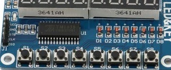
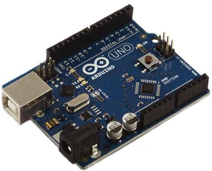
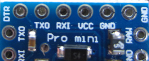
In a recent blog post, we introduced the TM1638 module – a device with multiple input, output, and display functionality available at a very reasonable price, and perfect for use with an Arduino board. Click here to buy TM1638 modules for under £2 delivered.

TM1638 Arduino Display Module

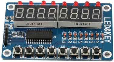
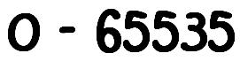
Of most interest to us was the pair of 4-digit 7-segment LED displays which can be driven by just three Arduino output pins (in addition to 8 LEDs and 8 input buttons). The majority of the products and bespoke devices we build and sell have a display to show measured voltages or temperature sensor readings. As the voltages measured are always from 0-35V, and the temperatures range from 0-99 degrees Celcius, we planned for each 4 digit display to show these values to two decimal places – e.g. a voltage of 12.45V (since the decimal point is included as part of the second digit unlike on LCD displays where the decimal point uses up a whole character).

An excellent and easy to use TM1638 library is available for Arduino, but did not have exactly what we needed. We want to be able to take any number from 0 to 99.9 and display it to either 1 or 2 decimal places on either the left or the right of the two 4-digit displays. In order to try and achieve this we wrote a simple rough and ready function which is provided in full at the end of this post for you to use, and is explained below.

Every one of the seven segments of each of the eight digits can be individually controlled for a total of 56 controllable segments. After installing and importing the tm1638.h library in a sketch and defining our module – refer to the excellent Introduction to TM1638 for details on getting started with TM1638 modules, the following code can be used to illuminate each of the segments on one digit each.

byte values[] = { 1, 2, 4, 8, 16, 32, 64, 128 };
module.setDisplay(values);

TM1638 module showing each segment being illuminated individually

The array of bytes values[] holds eight elements (values from 0-255) . The first element controls the first digit, the second element the second digit, and so on. So, the first element has a value of 1 and this illuminates the top segment of the digit. The second element has a value of 2 and this illuminates the top right segment. And so on all the way up to the eighth element which in this case has a value of 128 which illuminates the decimal point of the eighth digit.

In order to illuminate multiple segments of the same digit, you simply add together the values for the segments to be simultaneously illuminated for a digit, and enter that value in the array for the digit where you would like it to be displayed.

For example, the value to display an 8 (all segments of a digit illuminated) is 1+2+4+8+16+32+64=127. If you were to fill the byte array entirely with 127’s, the display would show eight number 8s in a row.

In order to follow a number with a decimal point, you add 128 to the byte value for the number you would like to display. For example, the number 1 is given by 2+4 (illuminating the two right side segments of the digit). To do 1. you add 128 to the byte value for the number 1 to give 134. Every 134 in the byte array will result in a 1. being displayed.

Now that we know how to display any number (or character) for any digit on the displays, all that is left to do is to take the 0-99.9 valued number, break it out into its constituent digits, and display them where we want them to appear on the display.

TM1638 module used as display for Arduino solar water heating pump controller

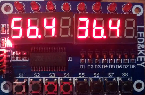
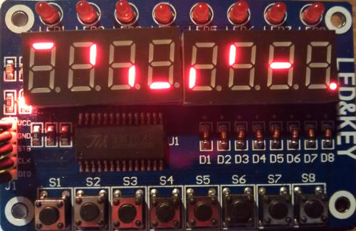
The above image shows the TM1638 module tested for use as the display for one of our solar water heating pump controllers. The value on the left is the solar panel temperature, and the value on the right is the hot water tank (or pool) temperature. In this example, we have displayed the sensor readings to 1 decimal place since the sensors are not accurate to 2dp, and if all eight digits are illuminated at the same time, it is not very easy to read the two temperature values displayed. (For our typical usage, it would be better if the two 4-digit displays were a couple of centimetres apart from each other, but other uses necessitate a full 8-digit display which requires them to be close together.)

TM1638 used as low voltage disconnect display with Arduino - showing voltage and status

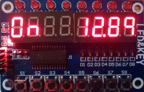
Above we have used the TM1638 module as the display for our 12V low voltage disconnect. In this case we only have one voltage measurement to display, but it is very accurate, so we have displayed it to two decimal places. That leaves us four characters to use to show system status information, in this case On (output is on because battery voltage is good). On is made with byte values 63, 84.

TM1638 module used as a display for an Arduino low voltage disconnect

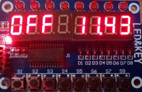
…and above we have Off as the battery voltage has been measured to be low. Off is made using byte values 63, 113, 113.

So, that just leaves the code itself. As mentioned earlier, it is quite ugly code – it could have been written more elegantly and efficiently, but it is fully commented and hopefully simple enough to understand and modify to your particular needs or  as a jumping off point for learning and for experimentation.

This sample code just displays a number (12.5432334) to two decimal places on the LEFT four digits of the display; but you can change the number, change the position, and change the number of decimal places by amending the contents of the loop() function. You can simultaneously display a number on the right of the display by calling the displayNumber() function a second time within loop() and having your chosen number displayed on the RIGHT.

If you try and display a number below zero or of 100 or over, the display will just show —- to indicate an error.

/*
 * REUK.co.uk February 2016
 * Displaying two 1 or 2dp values less than 100 on a TM1638 module.
 * 
 * An excellent starter guide to the TM1638 modules is available here:
 * http://tronixstuff.com/2012/03/11/arduino-and-tm1638-led-display-modules/
*/

// include the TM1638 library (which you must first install to your Arduino IDE).
#include <TM1638.h>

// Define a module on data pin 8, clock pin 9 and strobe pin 7
TM1638 module(8, 9, 7);

// Define constants for left and right so we can easily choose 
// which side of the display to show our number
#define LEFT 0
#define RIGHT 1

// displayDigits[0] = 63 which displays a 0
// displayDigits[1] = 6 which displays a 1
// displayDigits[2] = 91 which displays a 2...etc
// Add 128 to value to display the same number with a dp following it.
// e.g. display a 2 with 91, display a 2. with 91+128=219
byte displayDigits[] = {63,6,91,79,102,109,124,7,127,103 };

// An array for the values to be displayed - all zeroes means show nothing.
byte values[] = { 0,0,0,0,0,0,0,0 };

// The digits which will make up a number to be displayed
// e.g. 25.63 will fill theDigits array with values of 2, 5, 6, and 3
int theDigits[] = { 0,0,0,0 };

void setup(){
 // Start with the digital display blank.
 module.setDisplay(values);

 // Set the display to low intensity. High intensity is very bright and
 // uses more power.
 module.setupDisplay(true, 2); // where 7 is intensity (from 0 to 7)
}

void loop(){
 // This is an example number from 0 to 99.9999 you would like to display.
 float theNumberToDisplay = 12.5432334;

 // Where do you want to show the number, on the LEFT side, or the RIGHT of the display?
 int positionToDisplayIt = LEFT;

 // How many decimal places to show - must be 1 or 2 in this example code
 int numberOfDecimalPlacesToShow = 2;

 // Call the function to display the number
 displayNumber(theNumberToDisplay, positionToDisplayIt, numberOfDecimalPlacesToShow);
}

void displayNumber(float numberToSplit, int whichSide, int numOfDPs){
 // The number to be split should be a float from 0 to 99.9999
 // If is below zero or equal to or over 100, then just display ----.
 // numOfDPs is the number of digits after the point, only 1 or 2 are acceptable values
 if(numOfDPs > 2 or numOfDPs < 1)numOfDPs = 1;

 // Extract the digits from this number.
 numberToSplit = (int)(100 * numberToSplit);
 theDigits[0] = (int)(numberToSplit/1000);
 theDigits[1] = (int)((numberToSplit - (1000*theDigits[0])) / 100);
 theDigits[2] = (int)((numberToSplit - (1000*theDigits[0]) - (100*theDigits[1]))/10);
 theDigits[3] = (int)(numberToSplit - (1000*theDigits[0]) - (100*theDigits[1]) - (10*theDigits[2]));

 // Find and store the byte variables required to show these digits
 int dispDig[4];
 if(theDigits[0] == 0) dispDig[0] = 0; // Hide a leading zero if there is one
 else dispDig[0] = displayDigits[theDigits[0]];
 dispDig[1] = displayDigits[theDigits[1]] + 128; // Apend the dp onto the second digit
 dispDig[2] = displayDigits[theDigits[2]];
 dispDig[3] = displayDigits[theDigits[3]];

 // If we are only showing one DP, then leave last character blank to make things more legible on the display
 if(numOfDPs == 1) dispDig[3] = 0;

 // Make sure that the number passed to the function was >= 0 or <100, otherwise show an error with ----.
 if(numberToSplit/100 < 0 or numberToSplit/100 >= 100){
   for(int i = 0; i < 4; i++) dispDig[i] = 64;
 }

 // Find if number to be shown on the left or the right side of the display
 int offset = 0; // LEFT by default
 if(whichSide == RIGHT) offset = 4;

 // Update the values in the values array used by the display.
 values[0+offset] = dispDig[0];
 values[1+offset] = dispDig[1];
 values[2+offset] = dispDig[2];
 values[3+offset] = dispDig[3];

 // Update the display itself with the new values.
 module.setDisplay(values);
}

Pyboard Python for Microcontrollers

Pyboard python for microcontrollersPictured above is the Pyboard – an open source prototyping platform designed and manufactured in the UK. This board with its ARM microcontroller (STM32F405 clocked at 168MHz) is programmed using micropython a low memory usage version of the Python 3 scripting language.

The board has LEDs, microswitches, a built in accelerometer, and 30 general purpose IO connections (including 4 PWM, 14 ADC, I2C, and SPI pins) for connection to external components and analogue/digital sensors for your projects.

The board has 1MB of on board flash memory, 192KB of RAM, and also a micro SD card slot which can be used to store scripts and hold project generated data. It has a built in USB interface.

Pyboard fits in the marketplace somewhere between Raspberry Pi and Arduino. A Raspberry Pi is a full computer which means that it can be complicated to use, power hungry, and large in size. An Arduino is simple to use, has lots of useful GPIO and shields, and they are available in small versions, but they are not very fast and scripts need to be compiled on a PC before loading them to the Arduino. Pyboard is perfect for processor intensive stand alone projects – particularly for anyone who already has experience programming with Python.

Pyboard is just 33 x 40mm in size and weighs just 6g.

The official Micro Python website is here, and the tutorial which shows how to get strarted with Pyboard and Micro Python is here: Micro Python Tutorial.

Arduino Datalogger Testing

We recently built and tested a very simple SD card datalogger based around an Arduino Pro Mini – the smallest and cheapest Arduino board commonly commercially available. We have previously described datalogging to an SD card with an Arduino in our blog post Arduino SD Card Datalogging (to log temperatures). In this example we are instead logging the voltage of a solar charged battery used to power the lights in a shed.

REUK Arduino Battery Voltage Datalogger

The Arduino Pro Mini (£3) was programmed from a PC via an FTDI breakout board (£5), and connected to an Arduino micro SD module (£1) fitted with a 1GB micro SD card (£3).  Note that the unlabelled components in the image above are not required for this datalogger – we just built the controller so that it can later also be used as a low voltage disconnect.

We programmed the Arduino to read in the voltage of a 5Ah 12V SLA (via a 47K-10K voltage divider) and write it to a log file on the SD card once every second. The battery is connected to an 80 Watt PV solar panel via a solar charge controller. The battery is also connected to  three 1W LED spotlight bulbs which were left permanently on so that the battery would drain over night and be recharged during the day.

The datalogger was left connected to the battery from around 10:30am one day to around noon the following day in mid-April with blue skies both days.

USB memory card reader

In order to view the data collected on the micro SD card we just needed a USB all-in-one memory card reader (£1). Plug the micro SD card into the reader, plug the reader into a PC via USB, and download the collected data.

The collected data file (which was simply a list of voltages measured to 2 decimal places) was 97070 lines long with a file size of 680 kB. Therefore our 1GB card could have logged the battery voltage once a second for 3-4 years.

Looking through the datalog in a text editor it was obvious that the battery voltage did not change very fast at all. Therefore logging the voltage every second was unnecessary for this application – every 30 seconds or every 60 seconds would have been adequate.

Knowing from experience that plotting 100,000+ data points with Excel is usually an unhappy experience, I first copied the log file over to my Raspberry Pi, and ran the following sed script to create a new smaller file containing just every 60th record from the log file. (This is equivalent to having set up the datalogger to log the voltage once per minute in the first place.)

sed -n '0~60p' logfile.txt > 60slogfile.txt

This command took just 0.24 seconds on the Raspberry Pi (thanks to the raw speed of sed) and I then dropped the new smaller (1617 records) log file into Excel and made the following plot of the results.

Datalogger data collected from solar powered shed lighting

The vertical axis shows the measured voltage, and the horizontal axis shows time with the far left being 10:30am on day1 and the far right being noon on day2.

The plot shows how the solar charge controller carries out a bulk charge phase to rapidly charge the battery (peaking at 14.6V) and then maintains a float charge (around 13.6V) during the day while the solar generation far exceeded the charge used by the spotlights. At night the voltage of the battery drops rapidly down hitting a low of 11.95V before the sun rose high enough to start to charge the battery again.

If you need a voltage datalogger like this, a voltage datalogger with a built in low voltage disconnect to protect the battery from being too deeply discharged, or any other kind of single or multi-channel datalogger, please email neil@reuk.co.uk with details of your exact requirements.

Raspberry Pi GPIO with BerryIO

Today we have been trying out BerryIO – a control system for Raspberry Pi which is web browser based for ease of use and set up.

Although BerryIO can be used to monitor the system status of a Raspberry Pi; of most interest to use was the ability to easily control GPIO without any need for programming experience. This makes home automation via mobile phone, tablet, or desktop PC a realistic option even for relatively basic users.

Installation is achieved by entering the following commands at the prompt:

wget -N https://raw.github.com/NeonHorizon/berryio/master/scripts/berryio_install.sh
chmod +x berryio_install.sh
sudo ./berryio_install.sh

followed by:

berryio help

just to make sure it is working.

With BerryIO installed on your Raspberry Pi, you simply enter the IP address of the Raspberry Pi in the web browser on your phone, tablet, or PC, and after entering your Pi username and password when prompted you get a menu of options of which we found GPIO, camera (if you have one), and system status to be the most useful.

Raspberry Pi BerryIO - GPIO ControlSelecting GPIO from the menu, all of the GPIO pins are shown and you can set them individually to be either NOT IN USE, IN (for inputs), or OUT (for outputs).

BerryIO GPIO inputs Raspberry PiIf you select IN for a pin (for example GPIO-7) as shown above, when a high signal arrives on GPIO-7 the green light turns on, and when the signal arriving is low, the green light is turned off. The web browser updates the status of the GPIO pins in real time – therefore no need to refresh the browser for updates.

Raspberry Pi GPIO outputs controlled from web browser BerryIOIf you instead select OUT for a pin, a toggle switch appears below the selector. Click on ON to turn on the output (green light illuminates for that GPIO pin in the browser), or click OFF to turn off the output (green light turned off).

The system status shows a few bits and pieces of information about memory, storage, loads etc, but this does not currently update in realtime so you have to refresh the browser for the latest data.

raspberry pi system status - BerryIO

We will be looking into some useful real world useful applications for BerryIO, but it is certainly well worth installing it and having a play around with it just for fun.

BerryIO is still under development and new features and functionality are still being added to it. The release of an API for mobile app development should hopefully result in some interesting and useful tools being developed to control the Raspberry Pi remotely via a simple user interface.

Full details of BerryIO and the installation instructions are available here: install BerryIO.

Arduino SD Card Datalogging

We recently published our Arduino Solar Water Heating Pump Controller Design and Code which shows the basics of putting together a very simple solar water heating pump controller which you can then extend to add the other features you require. (Click here also for our Introduction to Arduino.)

The feature about which we have received the most questions is datalogging functionality to generate a log file of the temperatures recorded and the status of the pump (on or off).

Arduino SD card temperature datalogger

Pictured above is a demonstration on prototyping breadboard of how datalogging can be achieved using an Arduino SD Card Module (click link to buy). These are available from just £0.99 including delivery for standard SD cards (and from around £1.60 including delivery for modules for micro SD cards).

Arduino SD card reader moduleSD card modules for Arduino are very simple to use. SD cards operate on 3.3V, but the Arduino on 5V; however, these modules have all the necessary components fitted to bring down the voltages and enable safe reliable operation without the need for you to add any external components.

In the breadboard demonstration above, we have a single LM335 temperature sensor connected to the A0 pin of an Arduino Nano as per the solar water heating pump controller design (linked to at the start of this post).

We then have the following connections between the Arduino and the SD Card module:
Arduino D10 to SS (slave select)
Arduino D11 to MOSI (master out slave in)
Arduino D12 to MISO (master in slave out)
Arduino D13 to SCK (serial clock)
We also connected the 5V and GND pins of the Arduino to the corresponding SD Card module connections to power it.

Note that some SD Card modules have their connections labelled differently.
CS=SS, DI=MOSI, DO=MISO, and CLK=SCK.

For this demonstration we just want to create a text file (called templog.txt), measure the temperature once per second, and add each temperature reading to the end of the file to form a very basic datalog.

Arduino temperature datalogger sd cardThe stored data on the SD card can then be viewed, manipulated, and graphed on a PC. Multiple temperature sensors (or other sensor inputs) can be added and logged by extending the bare bones Arduino code above.

arduino rtc real time clock module

For a more advanced datalogger, the next key element to add is an RTC (real time clock). Using an RTC each data point can be logged alongside the exact time that it was recorded. Arduino RTC modules including a backup rechargeable button cell are available very cheaply. We will show you how add an RTC to an Arduino datalogger in a future post.

PICAXE Arithmetic Problems

Hitting the maximum number limit with PICAXE microcontrollers

In a recent post we showed our 24V Low Voltage Disconnect with Data Display. This device monitors and logs the voltage of a 24V battery bank, disconnects the output loads if that voltage is too low to protect the batteries, and has an LCD display on which the last 100 days of battery voltages can be checked, summarised, and the maximum and minimum recorded voltages displayed for analysis.

This device is built around a PICAXE microcontroller. These are simple to use and quick to programme microcontrollers, but they have a few ‘features’ which can make life difficult (sometimes making an Arduino a far better alternative). PICAXE chips can only process numbers in the range 0-65535, they cannot process negative numbers, and cannot process floating point (decimal) numbers.

In most cases those limitations are not an issue, but with our 24V LVD for example it was. The microcontroller is powered via a 5V regulator. In order to measure incoming voltages over 5V, a voltage divider (Wikipedia) is required – a pair of resistors connected in series with one end connected to the incoming voltage to be measured and the other end to 0V. The values of the resistors are chosen so that the voltage measured where the two resistors meet is in the range 0-5V across the full range of likely input voltages.

For our standard 12V low voltage disconnects we use a 47K resistor for R1 and a 10K for R2. The voltage output from this voltage divider is equal to R2/(R1+R2) multiplied by in the input voltage. So, if the input voltage is 13.00V for example, the voltage divider output voltage will be 13*(10K/(10K+47K))=2.281V which the 10-bit ADC on the PICAXE will see as (2.281V/5V)*1023=467. Only when the input voltage exceeds 28.5V will the voltage from this voltage divider exceed 5V, and 28.5V is never going to be seen from a 12V battery.

With our 24V datalogging LVD we chose 68K for R1 and 10K for R2. This gave an input voltage range of 0-39V corresponding to the ADC range of 0-1023 which is perfect for a 24V battery system. However, we hit upon a problem.

We work out what an input voltage of 1V corresponds to as an ADC value after passing through the voltage divider. With the 68K/10K divider on our 24V LVD, 1V on the input corresponds to an output of 0.12821V which corresponds to (0.12821/5)*1023=26.23. Therefore, if we divide the ADC value on the microcontroller by 26.23, we calculate the input voltage.

BUT, the PICAXE chip can only do integer arithmetic. An ADC value of 415 in this example corresponds to a measured input voltage of 415/26.23=15.8216V, but with integer arithmetic 417/26=15V so off by almost a full Volt.

In order to retain resolution and accuracy while forced to use integer arithmetic, we multiply the ADC reading by 100 and divide it by ten times the per volt ADC value. The result given is ten times the input voltage – for example (415*100)/262=158 which means 15.8V which is close enough to the actual value.

But, this approach can then lead to another problem. In the case of our 24V LVD with the 68K/10K voltage divider, when the input voltage exceeds just below 25V (which will almost always be the case with a maintained 24V battery bank), the ADC value is greater than 656. When we multiply this ADC value by 100 we get a number of over 65600 which the PICAXE (with its maximum number limit of 65535) cannot process. For example it will see 65536 as 0, 65537 as 1, 65538 as 2, and so on and will think that an input voltage of 25V is less than 1V which is not much use.

There are many (very complicated) ways around this maximum number problem using variables and/or the EEPROM to store parts of large numbers while doing calculations, but in the case of the 24V LVD with datalogger, all the internal data EEPROM was dedicated to datalogging, and all the variables were already being used. Therefore, instead of multiplying the ADC value by 100 and dividing it by ten times the per Volt ADC value, we modified our code to multiply the ADC value by 50 and divide it by five times the per Volt ADC value. This results in a small loss of accuracy of less than 0.1V at the upper range of predicted voltages, but works well enough for this particular device.

So, when choosing a voltage divider for an accurate voltage measuring device with a PICAXE chip, choose the resistors to ensure that the full possible input voltage range is more than covered, and also that any multiplication of ADC values in order to maintain resolution with integer arithmetic does not generate numbers over 65535. (Alternatively just use an Arduino with floating point arithmetic!)

Arduino Solar Water Heating Pump Controller Design and Code

Following on from our recent blog posts Arduino Solar Water Heating Pump Controller and Arduino Introduction, we have received a few requests for the source code (sketch) and design for a very simple Arduino based solar water heating pump controller.

We thought it would be an interesting exercise to show how just a few components and twenty or so lines of code can be turned into quite an effective controller, so here it is.

REUK.co.uk Arduino simple solar water heating pump controller - Arduino nano

For the schematic (and our own testing) we used an Arduino Nano, but pretty much any Arduino board could have been used. To that we just need to add a couple of LM335Z temperature sensors, a relay, an NPN transistor (we used a BC547), a few resistors, and a diode.

Here is a screenshot of the source code (the link to download it is at the end of this blog post):

Sketch for REUK Arduino simple solar water heating pump controller

This really is about as basic an effective microcontroller based solar water heating pump controller as it is possible to make.

The two temperature sensors connect to the (arbitrarily chosen) A0 and A2 analog pins, and the relay which switches the pump on and off to the D12 digital pin through a transistor (to limit the current drawn from the pin).

The variables diffON and diffOFF are used to set the number of degrees Celcius by which the solar panel must be hotter than the hot water tank for the pump to turn on, and then to turn off respectively. We used 6 degrees for diffON and 3 degrees for diffOFF – you may choose to use different values. These give hysteresis which prevents the pump switching on and off repeatedly and rapidly (since the temperature difference has to fall before the pump is switched off, and then rise before it will be switched on again).

The temperatures are measured every quarter of a second – delay(250) causes the programme to pause for 250 milliseconds. If the solar panel temperature is more than diffON degrees hotter than the hot water tank, the pump will turn on; and then when the temperature difference falls to diffOFF or lower the pump will turn off. And that’s it – simple, but does the job.

These LM335Z temperature sensors output a voltage of 2.73V + (X * 0.01V) where X is the temperature in degrees Celcius. The analogRead command digitises this analogue voltage to a whole number in the range 0 to 1023 with 0 corresponding to 0.00V and 1023 corresponding to 5.00V.

The calculation done on those analogRead 0-1023 values converts them into temperatures in degrees Kelvin. To convert degrees Kelvin into degrees Celcius you just subtract 273.15. That was unnecessary in this example since we are only interested in the difference between the two temperatures, but if you wanted to display the measured temperatures by connecting the Arduino board via USB to a PC that is how you would get them in Celcius.

Obviously there are a lot of things which can be added to this controller to make it more effective and reliable – e.g. time delays before the pump turns on and off, user programmability, manual override, frost protection, maximum temperature shut off, data logging and processing, and real-time temperature and system status display etc, but this is a good starting off point. There are vast amounts of resources online to help you learn more about Arduino – start with the official Arduino website to find out more.

Click here to download the Arduino source code for the REUK Simple Arduino Solar Water Heating Pump Controller as pictured above.

If you have any questions about the above or if you would like to share your modifications or enhancements to the code or design, please email neil@reuk.co.uk.

Arduino Introduction

We have been receiving a lot of questions about Arduino lately, so in this blog post I will attempt to briefly cover the topics about which we are most often asked – how to get started and which Arduino boards to use.

NEW – We are now publishing the full Arduino source code for many of our projects and products here: Arduino Projects.

The official Arduino website describes Arduino as an open-source electronics prototyping platform, and it is designed to be used by anyone interested in creating interactive objects or environments. We for example use Arduino primarily in a wide range of timers and controllers which act upon measurements made of the surrounding environment using sensors such as light detectors, temperature sensors, and many types of switches.

Arduino Uno board

For anyone getting started with Arduino we would recommend the Arduino Uno board pictured above which retails in the UK for around £20. It can be powered from the USB cable which is connected to a computer when uploading your sketch (Arduino program code) to the board from the Arduino IDE (see below), or via an external 7-12V DC power supply.

Click here to download the Arduino IDE (integrated development environment) software to your PC (Windows or Linux) or Mac. This is where you will write your sketches, communicate with your Arduino board, and find lots of useful example code.

There are a wide selection of alternative Arduino boards offering different features, numbers and types of inputs and outputs, and different physical sizes and prices. These are detailed on the Arduino website.

There are also a selection of Arduino Shields which connect to Arduino boards to give additional advanced functionality – e.g. Wifi, GSM, and ethernet connectivity, motor control, SD card slot for datalogging, real time clocks, LCDs, or simple prototyping boards for you to use for added external components and/or sensors.

arduino nano and pro mini

Pictured above are the Arduino Nano and Arduino Pro Mini. These small boards are excellent for embedding in projects thanks to their small size. The Pro Mini for example is a tiny 0.7″ x 1.3″ small.

The Arduino Nano retails in the UK for around £20-25, but as Arduino is open-source, much cheaper clones are available with prices starting at around £6 only including a USB cable and air mail delivery!

Clones of the Arduino Pro Mini are available from around just £3 each, but as the image above shows, this board does have a USB connection. In order to programme the Pro Mini you need a breakout board such as the one pictured below.

ftdi basic breakout board for arduino pro mini

This is an FTDI Basic Breakout For Arduino USB-TTL 6 PIN 3.3/5V. When you want to programme the Pro Mini, you connect it to this breakout board and connect that via USB to the computer. These boards are available from around £5.

FTDI board connected to Arduino Pro Mini board

Here are the labels on the Pro Mini terminals which are hidden in the image above to show what connects to the FTDI breakout board.

Connections for ftdi breakout board on arduino pro mini board

When programming is complete, you disconnect the Pro Mini and use it in your project, and you still have your breakout board. Therefore if you are doing a lot of embedded projects, the Pro Mini is the most cost effective Arduino board to use.

The other option for projects is to prototype using an Arduino development board, and then make an Arduino standalone. For this you programme the microcontroller on the board, and then remove it (possible with the Arduino Uno and older Duemilanove boards) and add it to your own circuitry. We detail this option here: Standalone Arduino on a Breadboard.

It is getting harder to find the Uno and Duemilanove boards now as they have been superseded with the latest Arduino boards which have surface mounted microcontrollers. But, you only need the one board for prototyping and programming, and when you have one, it is easy to get the ATmega328 chips with the Arduino bootloader pre-installed for your projects.

Here are some useful links to help you find the above described items:

Arduino Uno – Rev 3.0 boards with USB cable supplied. £17+ for official boards, or from £6 for compatible clones. Make sure to choose a ‘development board’ (not surface mounted microcontroller) if you want to remove and embed the microcontroller chip in your projects. See image below (development) compared to the surface mounted version at the top of this posting.

arduino uno development board

Arduino Nano – from £12 for official boards, and from £6 for compatible clones (mostly available with included USB cable). Note that headers are usually not soldered onto cloned nanos (so they do not spike through the package in the post), but will be included for you to solder.

Arduino Pro Mini – from under £3. Supplied with headers for you to solder.

FTDI Breakout – for the Arduino Pro Mini – you just need one which you can reuse. Prices from around £5.

Arduino Duemilanove – from £10 for clones, and up to £20 for official boards. Not many available now compared to the Uno.

ATmega328 – chip supplied pre-loaded with duemilanove bootloader or Uno bootloader (choose the correct one for your board). Comes with the clock crystal and capacitors required for an Arduino standalone.