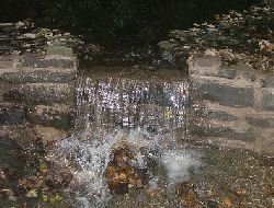
If you are fortunate enough to have a stream running through your land then you are blessed with a source of clean green renewable energy. In this article we will follow the construction of a complete DIY waterwheel power generation system.
Pete from Mawdesley in West Lancashire is an electronics engineer with good hands on ability with anything mechanical. With an interest in self-sufficiency, and a property with a stream running through it, the only logical thing to do was to build a waterwheel to generate electricity for his home office.
The stream crossing Pete’s property has a total head of 1.5 metres. However, to protect the neighbours from the noise of a waterwheel, there is 0.5 metres of usable head. He has estimated flow rates at just 1-2 litres per second (l/s) in the summer, 40-60 l/s in the autumn/winter/spring typically, and a whopping 200-1000 l/s when the stream is in flood after heavy rain.
Damming the Stream
First of all a dam had to be constructed in order to funnel the stream toward the waterwheel. (Where damming is not possible, a Run of River set up would have been used.) The dam created a 24 incheshead of water which passed through a gap equal in width to that planned for the waterwheel paddles – 2 feet.
During construction of the dam, two submersible pumps were used to divert water around a temporary ‘mud‘ dam with a sump hole in the front. The dam was built during the summer when the flow rate was at its lowest, and so the pumps were only on 5% of the time during the 24 hour period required to get everything built.
Constructing the Waterwheel
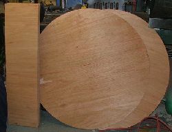
The waterwheel itself was constructed from 12mm marine plywood which typically comes in 8ft x 4ft sheets. It was these dimensions which dictated the final diameter of the waterwheel (1.2m = 4 feet), and the width of the paddles (0.6m = 2 feet, i.e. the size obtained when a plywood sheet is cut in half). Just two sheets were required for the complete waterwheel at a cost of around £30 per sheet.
The waterwheel is made up of 2 disks (the sides), and 12 paddles. Using 12 paddles makes it easy to mark out the location of each paddle on the wheel since they are separated by a 30 degree angle (= 360 degrees / 12). The paddles were chamfered to minimise the surface area of water hit by the wheel as it rotates, with the aim of making the waterwheel as quiet as possible in operation.
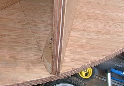
Above is an image which shows how the paddles were fixed to the disk of the waterwheel. Screws were used to hold everything together, but nuts and bolts may have been better to reduce the chance of structural failure. To add strength to the whole waterwheel, 8mm metal rods were fitted underneath every paddle. With all the paddles screwed in place and everything sealed, the basic waterwheel looked like this:
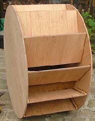
Even marine ply needs to be waterproofed if it is to last any length of time without rotting in water, so two coats of Thompsons Waterseal were used to seal the plywood. This was not really enough since the ply remains porous – so much so that when the water level drops and the waterwheel stops spinning, the bottom of the wheel absorbs water where it dips in the stream. The wheel then turns unevenly for a week or so due to the uneven weight distribution which greatly increases the wear on the bearings and is less efficient. That said, after one year of operation the plywood still looks as good as new.
The Framework
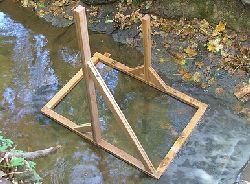
Any waterwheel needs a framework supporting an axle on which it sits rotating freely as the flowing water pushes it around. Lengths of brand new kiln dried 3″ x 2″ oak were used (obtained for free, otherwise a less expensive timber would have been used). The finished frame was bolted into the bed rock with 6 inch long M8 bolts as shown below during construction:
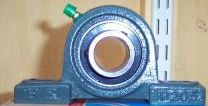
20mm bore pillow block self lube bearings (pictured below) were used for the axle (cost around £3.50 each from eBay UK – click here to search eBay for pillow block bearings).
Permanent Magnet Alternator
The permanent magnet alternator chosen for this project was the WindBlue DC-540 – an alternator typically used in low wind areas on wind turbines, but also well suited to hydro power applications (with suitable gearing). The alternator cost just over US$200 plus shipping to the UK (which took one month).
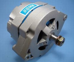
This alternator reaches 12 Volts output at just 150 RPM, and will charge a 12 Volt battery at 15 Amps at 2000 RPM. The manufacturers claim that this unit can “handle over 10,000 RPM with ease“.
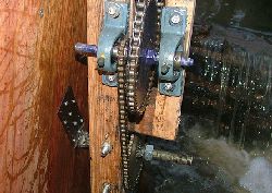
Since this waterwheel rotates at just 10 RPM, a roller chain and hardened sprockets were used to gear up the waterwheel output from 10 to 275 RPM (in stages of 1:4.5 and then 1:6 to give total gearing of around 1:25).
Smaller (12mm bore) pillow block bearings (pictured below – bearings are blue) were used to hold the sprockets in place.
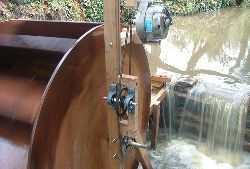
Waterwheel Video
Click below to watch the finished waterwheel in action after a good night’s rain – generating 5 Amps at 80 Volts = 400 Watts.
Using the Power
The WindBlue alternator comes with a built in bridge rectifier to turn the generated AC electricity into DC which can be used to charge batteries etc. Connections to the three phase AC output of the alternator are also provided so that an alternative (external) bridge rectifier can be used.
The 12 Volt battery bank consists of four 55Ah AGM deep cycle solar batteries connected in parallel for a total capacity of 220Ah at 12V. Currently 2.5mm equipment wire (multi-stranded copper) is used to connect the rectified DC output from the alternator to the battery bank 15 metres away. Since there is some voltage drop* through this relatively thin cable over the 15m run (a few percent), it will soon be replaced with thicker (10mm diameter) cable.
* Click here to try our automatic line losses calculator.
A Xantrex c35 controller (available from US$100+ new) is currently used as a charge controller to protect the batteries from overcharging. When the set battery full voltage is reached, the controller is configured to make an open circuit leaving the waterwheel (which then has no load on it) to free wheel. This could easily result in the waterwheel being damaged, and so a 12/24V resistive heater will soon be added as a dump load to be automatically turned on by the controller when the batteries are full.
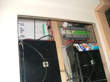
The generated electricity is split between a battery in the garage and the main battery bank (pictured above) which is located in a garden office (converted shed). The charge is split through a diode and power resistor (5 x 0.1 Ohm 10 Watt rated connected in series) with 0.25-1.25A typically going into the garage battery, and 2A-6A into the office battery bank. (There is also a 65W PV solar panel fitted to the roof of the house to keep the main battery bank charged during the summer).
In the office a 600 Watt modified sine wave inverter provides 230 VAC to power a laptop and TFT display. The battery in the garage is connected to a 200W pure sine wave inverter to power lighting.
(note that a modified sine wave inverter cannot typically be used with energy efficient CFL light bulbs).
Future Improvements Planned
Since the alternator generates high voltages at low RPM it would be more efficient to reconfigure thebattery bank to 24V or even 48V. This would also reduce the thickness of cable required between the alternator and battery bank, but would necessitate the purchase of (more expensive) 24V or 48V power inverter.
More Waterwheel Information
We have more information about waterwheels available in the following articles:
Calculation of Hydro Power
Introduction to Waterwheels
Electricity from Waterwheels