Additional Information
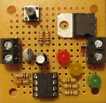
This is the REUK Super Timer 3 Mini – the small version of latest iteration of our REUK Super Timer.
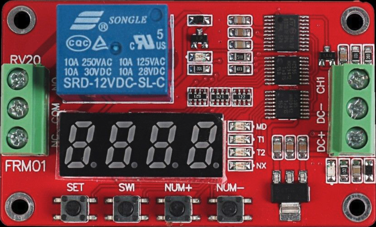
2018 Update – While we continue to sell our REUK Super Timer 3 Mini, for the vast majority of applications, we would highly recommend considering the FRM01 PLC Relay Timer Module which is pictured below. It has far more functions, is one-third the price of our Super Timer, and it works really well.
Unlike previous versions of the Super Timer, this MINI version does not have an onboard relay to switch external loads on and off. Instead this timer simply has an up to 1 Amp output which can be used to directly power external devices, or can be used to switch a standard or solid state relay to switch higher powered devices.
The previous versions of the Super Timer were 12VDC powered. This MINI REUK Super Timer 3 will accept any input voltage from 4.5 to 30 VDC and will output that same voltage when the timer is ‘ON’. Therefore this timer can be used with low voltage (e.g. 3 or more AA / AAA cells in series) projects, as well as with 12V and 24V systems.
Timer Modes
Version 3 of the REUK Super Timer offers four modes of operation.
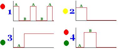
Mode 1 is the original repeating timer ON OFF ON OFF ON OFF where the user can set the ON time ‘A’ and the OFF time ‘B’.
Mode 2 turns the output ON when the timer is connected to power, and keeps it on for user set time ‘A’. Then the output is kept off until the timer is reset.
Mode 3 keeps the output OFF for the user set delay time ‘A’ and then turns it ON until the timer is reset.
Mode 4 keeps the output OFF for the user set delay time ‘A’, then turns the output ON for time ‘B’, and then turns the output OFF until the timer is reset.
Timer Connections
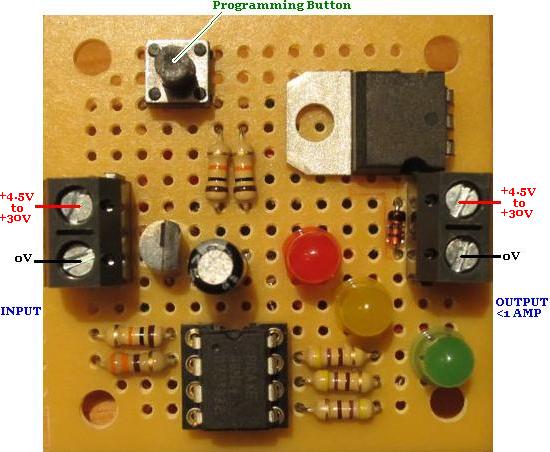
Pictured above is the connection diagram for the REUK Super Timer 3 MINI. Note the location of the programming button which is used to set the timing regime and select the mode of operation.
Programming the Timer
First of all select the timer mode 1,2,3 or 4 which you would like to use. To do this press and hold the button while connecting the timer to the power. All three LEDs will light up. Keep holding the button for one second and the LEDs will turn off – now release the button.
The currently selected mode will be shown using the LEDs. Red LED for Mode 1, yellow LED for Mode 2, green LED for mode 3, and both the red and the green LED for mode 4. Each press of the button now changes up the mode: mode 1 to 2 to 3 to 4 to 1 to 2…etc, and the LEDs will show which mode you have selected. When you are happy with your choice of mode, don’t touch the button for 5 seconds and the selected mode will be saved in memory.
Now you need to set the times ‘A’ and ‘B’. (Note that if you are in mode 2 or 3 you can set anything for time ‘B’ as that value will not be used.)
For the first 2 seconds after the circuit is connected to the power the yellow LED will flicker on and off rapidly. During this time it is possible to re-programme the durations ‘A’ and ‘B’. Press the programming button once and the yellow LED will turn off. This confirms that you have entered programming mode.
For ‘A’ and ‘B’ you must enter first the timing units (hours, minutes, or seconds), and the two digit number of those units – e.g. 03 or 47 (from the range 01 to 99).
Programming entails entering six numbers in the following order:
1) ‘A’ time units: 0 = hours, 1 = minutes, 2 = seconds
2) ‘A’ tens: e.g for a 43 second ‘A’, this value would be 4 (since 4 x 10 = 40). For a 1-9 second duration this value is 0 – e.g. 01, 02, 03,…09
3) ‘A’ ones: e.g. for a 43 second ‘A’, this value would be 3
4) ‘B’ duration time units: -as above-
5) ‘B’ tens: -as above-
6) ‘B’ ones: -as above-
To enter each value in turn, the technique is described below:
The red LED will light up for 2 seconds. If you want to enter a ‘0’ then press the button while the red LED is on. When the red LED turns off, the green LED will start flashing – on for 1.5 seconds, then off for 0.5 seconds. If you want to enter a ‘1’ then press the button while the green LED is lit for the first time. To enter a ‘2’, wait until the green LED turns on for the second time and press the button. To enter a ‘3’ press the button the third time the green LED lights up…and so on.
When you press the button the green LED (or red LED if you are entering a ‘0’) will immediately turn off, and the yellow LED will light up and stay on for one second. This gives you visual confirmation that your input has been accepted and tells you to get ready to enter the next value. When the yellow LED turns off and the red LED lights up again repeat as above to enter the next value.
If you make a mistake while programming, just disconnect the circuit briefly from the power and start again. It is much easier to programme the timer if you prepare yourself beforehand by working out and writing down the six values in order so that you are ready to enter them.
For example, if you want a (Mode 1) timer which will be ON for 7 seconds and then OFF for 23 minutes, the ON timer units are seconds (‘2’), and the OFF timer units are minutes (‘1’). Therefore you would need to enter the following sequence of values:
‘2’ (seconds – second green LED), ‘0’ (no tens- red LED), ‘7’ (7 ones – seventh green LED), ‘1’ (minutes – first green LED), ‘2’ (2 tens – second green LED), ‘3’ (3 ones – third green LED). So, you would write down
before you programme the timer – note that ‘red’ is written rather than ‘0’ so you remember to press the button when the red LED is on.
If you enter a number greater than 9 for the tens or ones, ‘9’ will be saved. If you enter a number greater than 2 for the time units, ‘2’ will be saved – i.e. your timer will be programmed in seconds.
When you have programmed all six values, the timer will save them and revert to standard operation – i.e. for whichever mode you have chosen, it will start its internal timer. When the output is ON, the green LED will be on, and when the output is OFF, the red LED will be on. If you have selected a mode which finishes with the output OFF, the green LED will blink when the timer has finished.
The programmed ‘A’ and ‘B’ times as well as the selected mode are stored in non volatile memory, and so will be retained even when you disconnect the circuit from the power. Therefore, you only need to go through the programming steps if you want to change the ON and/or OFF duration for some reason.
Timer Accuracy
The accuracy of the timer is better than around 1%, i.e. over the course of an hour the timer could gain or lose 30 or so seconds (usually far far less). Therefore the timer is not suitable for use where exact timings are required – e.g. if you want something to be turned on at exactly the same time every day (since the times will drift a little over the course of many days and weeks). In that case you would be better off with a programmable digital timer.