Timer for Poultry Egg Incubator

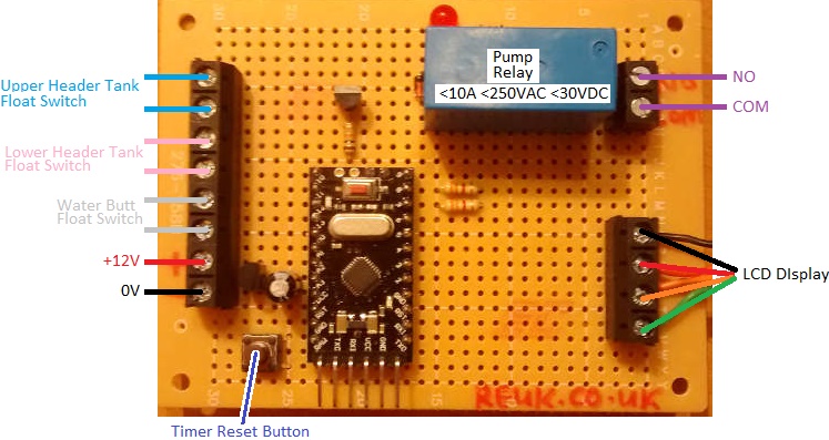
Pictured below is a timer we built to accompany a Poultry Egg Incubator Controller we made recently.

timer for poultry egg incubatorWhen incubating eggs it is very important to keep track of the time since they were laid since, for example, eggs must be turned regularly until the last few days before hatching, and for some eggs the temperature and humidity ranges need minor adjustments during the incubation period.

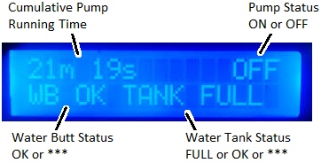
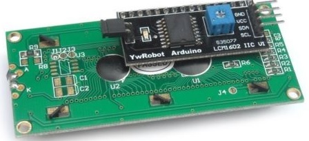
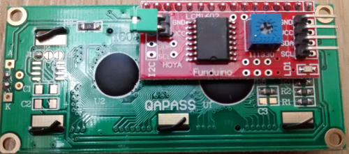
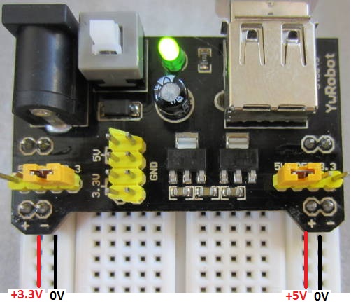
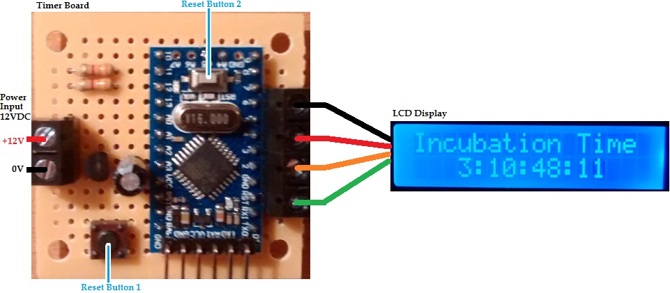
Our timer is 12VDC powered like the incubator, and has a display to show the elapsed time since it was last manually reset. The time is shown in days:hours:minutes:seconds format.

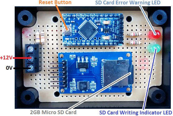
Since eggs take anything up to 6 weeks to hatch, the time elapsed is stored in memory on the timer microcontroller every 15 minutes so that if the power to the timer is cut for any reason (e.g. flat battery or accidental disconnection of one of the power leads), when the timer is reconnected to power, it will restart from within no more than 15 minutes of where it was before the power cut.

After incubation has finished, a reset button (Reset Button 1) must be pressed for 1 second to reset the timer to 0:00:00:00 ready for the next lots of eggs to go into the incubator.resetting poultry egg incubator timer

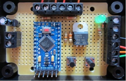
This timer is built around an Arduino Pro Mini. The microcontroller with its on board crystal keeps time well enough for this application. (If more accuracy was required we would have added a real time clock (RTC).). Reset Button 2 on the timer resets the internal clock which is limited to 4,294,967,295 milliseconds (just under 50 days) – plenty of time for pretty much everything up to ostrich eggs, but not long enough for emperor penguin, albatross, and some cuckoo eggs. For exotic eggs with very long incubation periods, an RTC would need to be added.

If you need a timer or a poultry incubator controller, email neil@reuk.co.uk with details of your requirements.

Poultry Egg Incubator with Humidity Sensor

Pictured below is a controller we recently made for use in a poultry egg incubator, designed to keep eggs within a very narrow specific temperature and humidity range for a few weeks. This is achieved using a heater, a fan, and a humidifier.egg incubator with humidity sensor, fan, heater, and humidifierThe eggs need to be turned at least three times per day every day except for the last few days before hatching. Previously we made a Controller for Poultry Incubator which had a motor which was turned on and off at different times of the day to turn the eggs. For this new incubator, the motor used is a very slow turning 12 VAC device makes 6 full rotations every 24 hours. That motor therefore did not need to be controlled with a timer – it is just left running at all times.

egg incubator controller status summary displayThe display for this controller shows the current measured temperature from the waterproof DS18B20 digital temperature sensor (read at 12 bit resolution = 0.0625°C resolution), and the humidity from a DHT11 sensor (within 5% accuracy). The DHT11 actually has a built in thermistor, but its temperature measurements are nowhere nearly accurate enough for this type of project.

The bottom line of the display shows the three devices being controlled – heater, fan, and humidifier respectively. In the image above, the heater is marked as being on. If the humidity level gets too low, the humidifier will be switched on. If the temperature gets too hot, the fan will turn on (and of course the heater will already be turned off by then).

Setting humidity range for poultry egg incubator

The user has full control over the thresholds at which the heater, fan, and humidifier will turn on and turn off. The temperature thresholds for the heater and fan can be set in steps of 0.2°C, and the humidity thresholds in steps of 2%.

For example, the heater could be set to turn on at or below 36.4°C and off again at or above 38.4°C. Then the fan could be set to turn on at or above 38.6°C and off again at or below 37.4°C. Humidity should ideally be around 60% (raising to 65% just before hatching), so the humidifier could be set to turn on at or below 56% and off again at or above 64% relative humidity.

display for egg incubatorWith all the thresholds programmed in by the user according to the requirements of the particular type of eggs to be incubated, a button can be pressed to show in turn the values programmed in – for example, above the humidifier is shown to be set to turn on at or below 43% RH and turn off at or above 70% RH.

Feb 2020 – We have now released the full Arduino sketch (source code) for this device here: http://www.reuk.co.uk/wordpress/full-arduino-code-for-poultry-egg-incubator-with-humidity-sensor/

If you need any kind of egg incubator controller (or the electronics for a temperature and humidity controlled humidor – functionally pretty much identical to an incubator!) – please email neil@reuk.co.uk with details of your specific requirements.

Rainwater Toilet Pump Controller with Display and Timer

Pictured below is a rainwater toilet pump controller which is different from those we usually make.

Rainwater toilet pump controller with display to show cumulative minutes that the pump has run.It is designed for a standard system which has two float switches in the header tank (one near the top and one near the bottom) as well as a float switch near the bottom of the water butt to prevent the pump running when there is no water to pump.

This particular controller also has a display which shows the status of the float switches and system status, and also has a built in timer which stores and displays the cumulative duration for which the pump has been running.

Display for rainwater toilet pump controller to show status and cumulative pump run time.With this timing information, and knowing the flow rate of the pump used, it is possible to easily calculate the volume of rainwater which has been supplied to the toilets and therefore how much mains water (and therefore money) has been saved with the system.

If you need any type of rainwater toilet system pump controller email neil@reuk.co.uk with details of your specific requirements.

Window Blind Motor Timer Controller

Pictured below is a device we made recently to control window blinds so that they automatically close in the evening and open in the morning to give the impression that someone is at home when they are away on holiday.Window blind motor timer controllerThe motor set up with these particular blinds is a small 3 Volt DC unit, but the controller is powered by 12 Volt DC. The motor needs to be turned forwards to open the blinds and turn in reverse to close the blinds. Therefore a pair of relays are used (as explained here: Reversing the Polarity of a Motor with Two Relays) to give the reversing polarity output for the motor.

A programming button is fitted to the device which is used to set the number of seconds that the motor is to run to fully open or fully close the blinds. In addition, there are a pair of microswitches which act as limit switches ensuring that if blinds reach the end of their motion before the expected time, the motor will be turned off so that it does not burn out under the heavy load of fighting resistance. Therefore, the motor runs until either the user programmed run time has elapsed or the limit switch is hit. If there was not a time limit, then if the blinds became jammed, the limit switch would never be reached, and again there would be the risk of the motor burning out.

If you need any type of motor controller or timer, please email neil@reuk.co.uk with details of your exact requirements.

LED on Import Electricity Meter Used to Turn on Immersion with Exporting

In our article Flashing LED on Electricity Meter we looked at how the status of the LED on an electricity meter in a grid tied solar PV system can be used to decide when to turn on a water heating immersion heater to use surplus solar generated electricity rather than exporting it.

When there is a dedicated export meter with an LED which flashes at a rate proportional to the power currently being exported, things are relatively simple, but for one client recently we had to deal with a system including only a standard domestic import meter. This has an LED which flashes at a rate proportional to the amount of electricity currently being imported (i.e. purchased from the National Grid), and which is permanently on while electricity is being exported.

Export meter for solar PV system LED detection circuit to power immersion with surplus power

The client wanted a device which would turn on his immersion (standard 3kW element, but powered via a power reducer which halves the power consumption to 1.5kW), after a user programmable number of minutes of continuous electricity export. The exact number of minutes desired for efficient operation was unknown, so we made the device programmable – i.e. the user could themselves set the number of minutes of continuous export required before the immersion would be turned on.

The immersion would then remain on until 5 seconds of the import meter LED flashing. Therefore, if turning on the immersion results in electricity being imported, the immersion would be turned off within 5 seconds, so very little electricity would be imported to power it. While the amount of electricity taken by the immersion is insufficient to use up the full export surplus, the immersion would stay on, heating water.

Surplus solar PV immersion controller using export meter LED to decide when to turn on immersion

Obviously this is not the most efficient system possible – something with a current sensing clamp to detect the exact level of import or export power is better, but the commercial options with this feature start at around £130.

This simple and easy to install system ensures that on a sunny day when no-one is at home using a high powered appliance such as a kettle or washing machine, surplus electricity from the solar panels will always be used to heat water rather than being exported (for which just a few pence would be paid), resulting in a payback period measurable in months.

The status of the LED on the meter (on or off) is detected using a simple light detecting resistor (LDR).

If you would like something like this device, please email neil@reuk.co.uk with details of your requirements.

i2c Address Problems with eBay 16×2 LCD Modules

arduino i2c 16x2 LCD display module

At REUK we use a lot of 16×2 LCD display modules of the type pictured above (and available here: 16×2 LCD Arduino Module  from just £3) for some of the products we sell in the REUK Shop and more often in our bespoke products.

These units have a standard Hitachi HD44780 compatible 16 x 2 character liquid crystal display (LCD) to which is pre-soldered a small controller board (in the pictured example from YwRobot) enabling [i2c] communication between the LCD and an Arduino or Raspberry Pi over just two wires (plus two more wires for the power inputs). In the case of the Arduino, pin A4 connects to SDA on the module and pin A5 to SCL.  Many Arduino libraries (e.g. LiquidCrystal_I2C) are available which have typically made these LCDs very simple to set up and use even for beginners.

In all of the example code for these libraries, the default address on the i2c bus for these LCDs is always given as 0x27, and so after years of using them, and it always being correct, it just became automatic to expect it to be true.

Funduino Arduino LCD display module

However recently (since April 2015) the small modules on the backs of the available displays have suddenly changed from being red (Funduino – pictured above) to being black (YwRobot) – probably because the YwRobot modules are cheaper than the Funduino units.

In general, the YwRobot modules work identically to the old Funduino units with one key difference. We have found that approximately one unit in five (including from different suppliers) is not preset with 0x27 as its address meaning that we have had to modify our long established, tried and tested Arduino code to get them to work.

In the most part we have (after some research) found that the address 0x3F works with these units, but we have also had a few units for which neither 0x27 nor 0x3F works. In those cases we have to use the i2c scanner sketch to find out what the address is for each particular display which is a pain. The main problem is that almost none of these units are supplied with any accompanying documentation, and those that do always state 0x27.

If you have had similar problems, please email neil@reuk.co.uk with details of the address you have discovered for the display(s) you purchased and the source of the display(s) so that we can build up a comprehensive reference document to help people who have purchased a display and have no idea of its address. The consistent 0x27 addressed Funduino units are getting harder to source and don’t seem to be coming out of China any more.

Heating Circuit Pump Controller

Pictured below is a controller we recently made for a wood fire cooker based heating circuit.

heating circuit pump controllerThe controller itself is physically identical to our standard 2014 Solar Water Heating Pump controller with an LCD to display temperatures and system status and a couple of ds18b20 digital temperature sensors. However, it has been completely re-programmed for an alternative use.

The customer has an Esse wood fired cooker with a 2.5kW domestic water circuit. This thermosyphon water heating circuit feeds a 140 litre thermal store in which a heat exchanger is used to heat up domestic hot water.

As there is some surplus heat over domestic hot water requirements, a pump is required to divert surplus heat to a panel radiator situated below the tank.

Two temperature sensors are to be fitted – one in the middle of the storage tank and the other on the return thermosyphon flow to the cooker.

The controller we put together for this system measures the temperature of the two sensors, and if both are found to be above user set values (for example, 80C for the tank and 45°C for the return flow), then the pump will be turned on to divert hot water to the radiator. When either of the two sensor temperature subsequently drops 2°C or more below the set values, the pump will be turned off sending hot water back into the storage tank.

If you need any type of water heating system controller, email neil@reuk.co.uk with details of your exact requirements.

Voltage Measuring Datalogger with micro SD Card

Pictured below is an Arduino-based datalogger we recently made for measuring the voltage output of induced EMF in coils through which a magnet is passing. The voltage output needs to be logged once per second for up to a few hours.

SD card dataloggerThis particular datalogger is 12VDC powered, and will measure and log voltages up to 15VDC. (The induced voltage to be measured in this project has been measured with an oscilloscope not to exceed 5V).

Each time the datalogger is connected to the power source and to the coil to be measured, a new log file is created on the supplied 2GB micro-SD card. An on board reset button can also be used to start a new log file.

On start up or when reset, the SD card is initialised and checked to ensure that it is present and working properly. If it is not, the red LED turns on and stays on to warn the user – there are few things worse than running an experiment only to find that no data was collected. If all is well with the SD card, then once every second the coil voltage is measured and appended to the latest log file.

When the experiments are complete, the SD card can be removed from the datalogger and accessed via a PC for processing and analysis. The generated datalog files are simple text files with each measured data point on a new line in chronological order.

If you need a datalogger,  email details of your exact requirements to neil@reuk.co.uk.

Solderless Power Supply Module for Breadboard

We recently came across this handy little power supply module designed and built for use with prototyping breadboard (MB102 size) by YwRobot in China.

breadboard power supply moduleThis is a very useful device for anyone getting started with electronics thanks to its low cost (approximately £1 delivered) and ease of set up and use.

The module simply plugs into a breadboard and gives two pairs of rails which can be configured to give you 2x5V rails, one each of 5V and 3.3V, and you can also set one or both pairs of rails to 0V.

mb102 breadboard power supply modulePictured above we have used the small yellow jumpers to set one pair of rails to 3.3V/0V, and the second pair of rails to 5V/0V. The board is then ready to supply a few hundred mA at 3.3V and 5V to any project you may want to prototype/build on the breadboard.

The module is powered via USB. Virtually everone now has a micro-USB charger at home for mobile phone and table charging etc, so it is surprising that they chose to use a full size USB-A connector. It would have been much better to go for a micro-USB connector.

The module has two low drop linear voltage regulators to supply the 3.3V and 5V outputs. When we tested this with a USB power supply outputting 5.46V, we measured 5.123V on the 5V rail, and 3.286V on the 3.3V rail.

If your USB power supply provides less than 5V (or more likely, you have less than 5V after losses in a long/cheap cable) the 5V rail will always be a few tenths of a Volt lower than the incoming voltage – therefore you cannot guarantee a reliable 5.0V output from this module when powered via USB. Similarly, it is best not to use this connected to a USB port on a PC as the voltage of PC USB ports can jump around a lot depending on what the PC is doing at any particular instant.

There is however a standard DC barrel jack for DC input power. Using a standard 6V DC power supply should give you a full stable 5V output from the module.

There is an on/off switch on the module, with a green LED to show the current status. This is useful not just because it saves you from having to unplug or switch off your USB power supply at the power point, but also because the capacitors in a power supply retain charge after you unplug the power supply and this charge will feed through the module into your electronics project until those capacitors have discharged. That could have unforeseen consequences as the voltage input to your circuit drops.

The quality of the components used and the build quality are as you would expect from a product offered at such a low price, but these modules are still an excellent first purchase for anyone interested in circuit prototyping.

These modules are available on their own, or together with a suitable breadboard and jumper links as a complete starter package. Click here for more information or to make a puchase of one of these power supply modules.

Dawn Dusk Hen House Door Controller with Timer Override

Pictured below is a hen house door controller we recently made for a customer which is a modified version of our standard Dawn Dusk Hen House Door Controller.

hen house door controller with light detector and timer overrideThis controller will automatically open a hen house door at dawn and close it again at dusk. Dawn and dusk are detected via a light detector, and the user can calibrate the light level at which they consider it to be the transition between day and dusk and between night and dawn to meet their needs.

The modified version pictured above has the additional benefit of a programmable digital timer. We make hen house door controllers with light detectors which automatically detect dawn and dusk, and we also make them with programmable digital timers so that the user can instead set the exact time that the door is to open and close. This particular controller is our first which has both a light detector AND a programmable digital timer for maximum flexibility.

The purchaser of this controller expressed a wish to be able to have the hen house door close at dusk automatically, but also to be able (sometimes) to open the door later (or even earlier) than dawn. Therefore, in the summer when dawn could be at 4am, the timer can be used to keep the door closed until 6am or later to keep the noise down and avoid disturbing neighbours. The programmable digital timer we used can be set with different timings for weekdays and weekends, so for example, the door can be kept closed until much later in the morning on the weekend to keep the noise down.

If you need any kind of poultry door controller, email neil@reuk.co.uk with details of your exact requirements.