Timer to Protect Solenoids Used in One Man Band Drum Kit

We were recently commissioned to design a device to protect the solenoids used as components within a one-man band drum kit. Rather than wearing the drums on the back, this drum kit is made to sit alongside the one-man controlled by foot pedals leaving hands free to play the guitar or a keyboard.

Each foot pedal contains two micro-switches. Rocking the foot backwards and forwards, the heel and toe trigger those switches which activate solenoids which pull a cord which impacts the drumstick on a drum. A bass drum could be connected to the toe switch and a snare drum to the heel switch on one pedal, and a second pedal could control the high hats for example enabling complicated rhythms to be played.

This system all works well except that if the foot is left resting on the pedal so that one of the micro-switches remains closed, the solenoid will burn out. It is also difficult to depress a micro-switch for the correct length of time so that the drumstick hits the drum and bounces immediately off rather than being left pressed against the skin of the drum affecting the sound.

The timer we came up with detects when a drum pedal micro-switch is pressed. It then supplies an output to the solenoid for exactly 0.10 seconds (which has been proven experimentally to be the perfect length of time with this setup). The solenoid will not be activated again until after at least 0.40 seconds has passed and also the micro-switch has been seen to be released before being pressed again. Therefore, if the micro-switch is kept pressed down, the solenoid will not be activated (and not kept activated) and so it will not burn out.

Solenoid protection timer for single drum

Pictured above is the first prototype unit used for testing purposes with one drum pedal micro-switch and one solenoid only.

Pictured below is the control board for three foot pedal inputs and three solenoid outputs, so heel and toe in one foot pedal and heel or toe in a second foot pedal to control three drums.

Solenoid protection timer for three drums

If you need any type of timer controller device, email neil@reuk.co.uk with details of your requirements.

Automatic Scarecrow Motor Timer Controller

Pictured below is the controller board we made for an automatic motorised scarecrow used to scare pigeons and crows from an orchard.

Timer Controller board to automatically run a motorised scarecrowThis scarecrow has two arms. As a motor turns, the arms flap up and down which scares birds away. We designed this device so that the orchard owner can set a motor running time of 1,2,3,4,5…etc seconds, and then a waiting time of 5,10,15,20..etc minutes before the scarecrow operates again. User programmability is important to enable optimal settings to be found to make the scarecrow as effective as possible.

If a motorised scarecrow is left with its arms up or out to the side, they can catch the wind which can lead to the scarecrow being damaged during bad weather. Our controller protects against this. When the motor running time countdown has finished, the motor continues to run until a microswitch detects that the arms are in the down position. The motor then stops.

Crows are dawn and dusk feeders, whereas pigeons are day feeders. Therefore the scarecrow is only required to operate from the start of dawn until the end of dusk. To that end, this controller includes a light detector, and the operator can calibrate the ambient light level above which the scarecrow will operate.

If you need any kind of timer controller, email neil@reuk.co.uk with details of your requirements.

Target Shooting Timer Controller to Replace Jackcast

Original JackCast shooting timer controllerPictured above is an old Jackcast shooting target timer controller which needed replacing. This timer could be set to repeat sequences 1-8 times or forever, the target edge times to 1, 2, 3, 5, 7, 10, 15, or 30 seconds, and the target face times to 1, 2, 3,4, 5, 6, 8, 10, 15, 20, and 150 seconds. Buttons are provided to manually face or edge the target, and there are start and stop buttons to run and stop the timer.

Pictured below is the Arduino-based replacement controller board we built to replicate the features of the original unit.Display for target shooting timer controllerThis will be fitted into an enclosure with panel mounted buttons, and the display as shown below mounted to show system settings and the timer status.shooting-target-controller-display

Here are some photographs of the finished controller installed into its case and connected up by its owner ready for use.

shooting-target-controller-panel

shooting target controller fitted into enclosure

Wireless operation has been added in parallel to the hard wired output from the relay on our controller. The right hand board above provides this functionality.

shooting-target-controller-connections

If you require any kind of shooting target controller, email neil@reuk.co.uk with details of your specific requirements.

Converting Digital Watch into a Timer Stopwatch for Projects

Pictured below are the inner workings of a cheap digital watch which has been modified to enable remote operation of the buttons so it can be used for automatic stopwatch timing.

Modified digital watch used as stopwatch with remote buttons or relay control

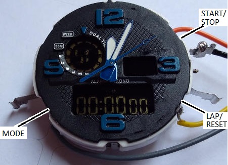
This particular watch had a broken backlight and broken strap, but it had always kept very good time. Therefore it was a perfect candidate to be re-purposed.

The watch had rubber button tops integrated into the watch case. When the workings are removed from the case, the buttons themselves are exposed. They comprise a thin strip of metal separated from a metal pad on the watch PCB. When the rubber button top is pressed down, the metal strip makes contact with the metal pad making an electrical connection.

Inside look at a digital watch button

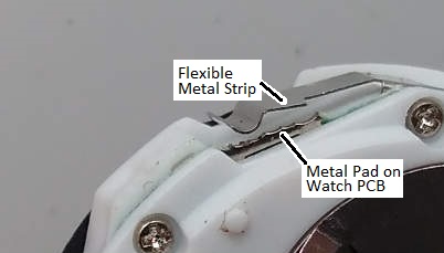
All of the metal strips are connected to the watch battery ground, so the watch detects button presses by waiting for 0V to appear on one of the metal pads (which are electrically connected to the microcontroller inside the watch).

We soldered wires to the three metal pads of the buttons we wanted to control, and a ground wire to one of the commonly connected metal strips. Shorting the end of this ground wire to the end of any of the other wires causes the relevant button operation to take place.

relay board to control a stopwatch for timing arduino projects
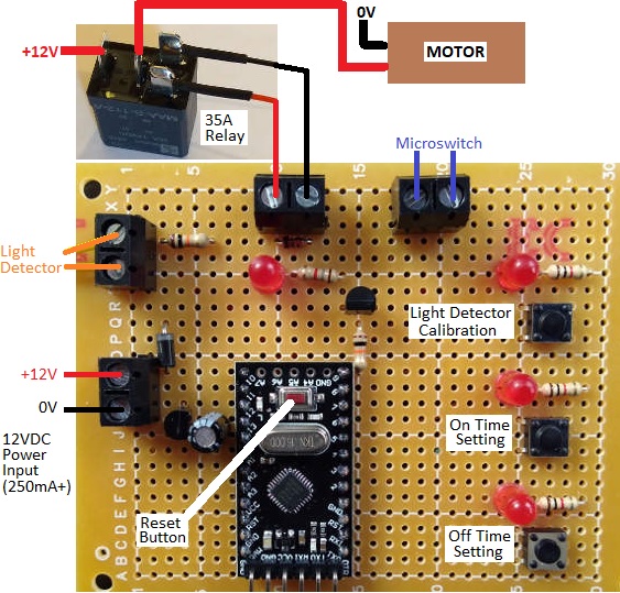
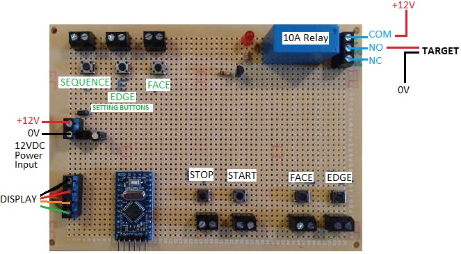
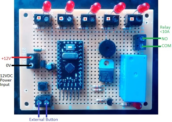
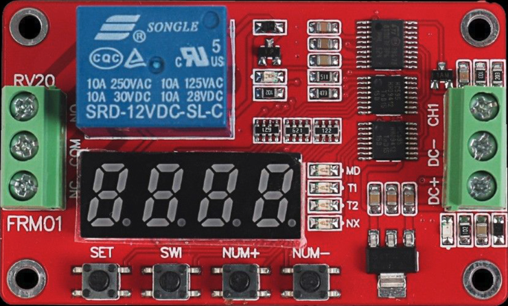
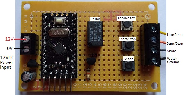
We next made the above pictured board. We put three tactile switches on the board and wired them up so that when pressed, they would short a mode button input to ground. These tact switches make it much easier to interact with the wired-up watch manually.

Then we added a small 5V coil relay and connected its NO and COM pins to the Start/Stop button connection and to ground for the watch. When the relay is energised (closed) it will simulate the Start/Stop button of the watch being held down.

The final component is an Arduino Pro Mini in a socket. This board will be used to calibrate the internal clocks of Arduino Pro Mini clones as their crystals are not accurate enough for some of the projects we build.

(Note that we are powering this board with 12VDC for convenience as that is the voltage we use for all of our testing rigs with a bench power supply, but for a one off it would have been 5VDC powered – 4 AA cells for example.)

Controlling the Stopwatch via Arduino and Calibrating the Arduino’s Internal Clock

 digitalWrite(relay, HIGH);
 delay(50);
 digitalWrite(relay, LOW);

The Arduino code above is used to briefly energise the relay which starts and stops the stopwatch. We used a 50 millisecond delay so that the relay has time to energise (physically close its internal contacts) and button presses of under 20 milliseconds were ignored by this watch. When someone presses a button, they typically keep it held down for from 30-70 milliseconds, so we replicated that.

To roughly measure how long is 10 seconds for the Arduino, we used the following code:

digitalWrite(relay, HIGH);
delay(50);
digitalWrite(relay, LOW);

delay(10000);

digitalWrite(relay, HIGH);
delay(50);
digitalWrite(relay, LOW);

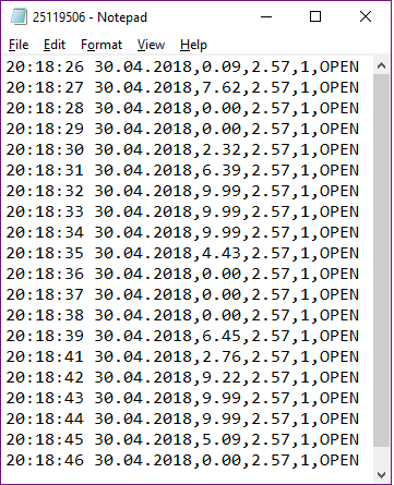
It starts the stopwatch, waits 10,000 milliseconds, and then stops the stopwatch. If the Arduino is accurate, the stopwatch will stop with 10.00 seconds displayed. In a few quick runs we got 10.03, 10.07, 10.06, 10.06, 10.03, 10.03, and 10.06 seconds. This seems to show that this particular Arduino Pro Mini was running a little slow (it could also be that it takes longer for the relay to energise than de-energise which could be significant when only timing 10 seconds).

The delay() function is not accurate in general since we do not know how long the loop execution time is. Instead for accurate time testing we use millis().
Replacing delay(10000); with the following:

unsigned long startTime = millis();
do{
  delay(1);
} while (startTime + 10000> millis());

we got 10.00, 10.00, 10.00, 10.00, 10.00, 10.00, and 10.00 seconds on the stopclock in initial testing.

For calibration we test for a minimum of 8 hours, but sometimes 12 or 24 hours. The longer the test, the greater the accuracy of the results and therefore the better we can calibrate the Arduino’s internal clock.

There are 28800000 milliseconds in 8 hours for example. So we’d modify the code above to have while(startTime + 28800000 > millis()); . After 8 hours, the stopwatch will show a time. We found that that this Arduino Pro Mini was running 4 seconds slow….so after 8 hours the clock showed 8h 00m 04s.
There are 28,000 seconds in 8 hours, so the error in the Arduino clock is
1 – 28,000/28004 = 0.0001428 = 0.01428%.
We can save this percentage error in memory on this Arduino Pro Mini and take it into account when using it in timing applications. If we want to use this Pro Mini to time 5 hours accurately, we’d run the timer for 5 hours minus 0.01428% of 5 hours.

Modified Spot Welder Timer from 555 Circuit

555 timer for weldingPictured above is a standard circuit design for controlling a spot welder for use in building battery packs and other applications. The welder is 12VDC powered from a large battery, and the 555 timer circuit controls the duration of the brief (sub one second) pulse of high current required to perform the spot welds.

We sell a selection of programmable timers with displays which are much simpler to use and set up than a 555 timer circuit with just a potentiometer used to set the current pulse duration. One of these user programmable options is our dual pulse welder timer controllerhttp://www.reuk.co.uk/wordpress/dual-pulse-spot-welder-timer-controller/ . A dual pulse when spot welding gives much better results, but requires a complicated circuit and many components to achieve using a 555 timer.

Therefore we put together the following controller which can work with the output side of a standard 555 spot welding circuit to give much better control and dual pulse capability for customers who already have an array of power MOSFETS set up to supply current to their 12V welding apparatus.

modified welder timer circuit based around old 555 timer circuitry, but giving dual pulse capability

The duration of the first pulse, pause, and second pulse can each be set by the user from 0.01 to 1.99 seconds duration with 0.01 second resolution facilitating consistent welds which can be reproduced again and again.

If you need any kind of spot welding timer controller, please email neil@reuk.co.uk with details of your requirements.

PPC 1500 Target Shooting Timer

PPC 1500 target shooting timer controller relay

Pictured above is a timer we recently built to control the start and finish horn for PPC 1500 shooting competitions.

In competition a button is pressed followed by a 3 second delay. Then the timer begins counting down from 8 secs,12 secs, 20 secs, 35 secs, 90 secs, or 165 secs with a horn sounding for 0.75 seconds as the timer starts, and again for 0.5 seconds after the timer has finished.

The user can select the timing option using the on board button, an external button, or using a remote control switch.

The on board display shows the current setting while the timer is not running, and then shows the countdown ticking down while it is running. The start button can also be used to stop the timer when it is running to reset the system.

A second button enables the user to sound the horn at any time while the button is being pressed.

If you need any time of timer controller, please email neil@reuk.co.uk with details of your specific requirements.

Formula 1 Race Starting Lighting Timer

formula 1 racing timerPictured above is a timer we recently built for a customer which will be used in a Formula 1 style race start lighting gantry. This gantry will be fitted at the top of a slope with toy cars held by a small gate latched up by a small solenoid with a spring loaded core. When the race is to start, the solenoid is energised which drops the gate allowing the cars to roll down the slope in their race.

In the photograph, five red LEDs are temporarily attached to the timer board for testing, but these will be mounted into the gantry across the track when it is finished.

When the user presses the button, the LEDs follow the standard F1 race start sequence – each red LED turns on in sequence with a one second interval. As each LED turns on, an on board piezo buzzer briefly pips. Then, when all five LEDs are illuminated, there is a random time interval of between 1 and 3 seconds before all the LEDs are turned off.

formula 1 race starting gantryThe lights turning off indicates that the race is to start. The buzzer sounds for 1 second, while the on board relay energises for 1 second to energise the solenoid and start the race.

Another Race Starting Timer

Pictured below is another similar race starting timer we made which controls three powerful lights via external relays.

3-light-formula-one-start-timerWhen the start button is pressed, there is a five second delay, then the three lights turn on one by one at one second intervals. After a random 0.5 to 4-5 second delay, the lights all turn back off.

If you need any kind of bespoke timer or controller, please email neil@reuk.co.uk with details of your requirements.

Dual Pulse Spot Welder Timer Controller

Pictured below is our popular 12VDC dual pulse spot welder timer controller which we designed, build, and sell.dual pulse spot welder controller

Spot welding (resistance spot welding – RSW) is used to join metal surfaces by passing a large electric current through them. Because of the heat generated by the resistance to the electric current, the contacting metals melt together forming a weld at the spot through which the current is passing.

In order to get good clean reliable welds and not to burn holes through the metal, it is essential that the pulse of electric current is of a suitable duration which depends on the types and thicknesses of the metals to be welded as well as many other factors. Therefore an accurate timer controller is required for consistent welds.

For the best spot welds, a dual pulse controller is used in which the electric current flows for a time (pre-weld), then there is a brief pause, and then electric current flows again (welding). The first pulse clears away any plating or surface oxidation, and then the second pulse welds the now clean base materials together. Using a dual pulse welder also reduces spitting.

REUK Dual Pulse Spot Welder Controller

Our controller offers two modes of operation: single pulse mode and dual/double pulse mode. Pictured below is a view of the built in OLED display when in dual pulse mode.

dual pulse spot welder display

The user can set the durations of Pulse 1, the pause time, and Pulse 2 in 0.01 second steps between 0.01 and 1.99 seconds.

single pulse operation of spot welder

In single pulse mode, the duration of just one pulse has to be set by the user. (A future update of this device will probably include up to 10 user-programmable presets for increased convenience.)

setting spot welder pulse duration

On board buttons are provided for toggling between the single and double pulse modes, entering programming mode to set the timings, and making a spot weld with the displayed settings. Screw in terminals are provided so that external buttons can be connected – for example a foot pedal to make a weld with your hands free.

This version of the welder controller is fitted with a 10A relay which can be used to power a < 5A rated solenoid which in turn switches the welder.

Buy a Welder Timer Controller for Your Relay

For any type of welder timer controller, please email neil@reuk.co.uk with details of any special requirements. Our controller as described above is available at £21.95 plus postage.

If you require a timer which will be switching more than 10 Amps of current for your welding setup, then we also make the alternative devices pictured below which have a 1 Amp 12V output for connection to your own solid state relay (SSR) or mechanical relay. These are available for £19.95 plus postage – no relay included. Click here for a source of solid state relays.

reuk dual pulse welder timer controller for solid state relay

dual pulse welder timer with solid state relay (ssr)

If you require a bespoke device which pulses the welder with very brief times and higher time resolution – e.g. 0.001s – 1.999s instead of 0.01-1.99s – we can modify the above photographed timer controller…but only for use with a solid state relay (since SSRs can switch in 1ms (0.001s) rather than the 10’s of milliseconds it can potentially take a mechanical relay to switch). Contact us with details of your specific requirements for a quotation.

Dual Pulse Spot Welder Timer Instructions

There are two buttons on the controller. If you press the ‘down’ button, you can toggle between single pulse and dual/double pulse operation. The display will change to show which mode you are in: SINGLE or DBL (double) as well as showing the durations currently programmed into the device.

If you press and hold the down button for more than one second, the display will show SET TIMERS. If you are in single pulse mode, you can now set the single pulse duration. If you are in double pulse mode you can now set the durations of pulse 1, the pause time, and pulse 2. The top line of the display will show what is currently being programmed (Time 1, Pause Time, or Time 2), and the bottom line will show the current value. Use the up and down buttons to increase or decrease the displayed value (within the range 0.01s to 0.99s). Five seconds after you last touched a button, the top line of the display will show -SAVED- and the value will be saved in long term memory (still available the next time you power on the controller). If you are in double pulse mode, you will now be asked to set the pause time and the duration of the second pulse in exactly the same way that Time 1 was set. (When using the up and down buttons to increase or decrease a time value, you can press and hold the button to move faster through the numbers.)

If you press the up button, the controller will run. The relay will close for the duration of Time 1 and then open again. If you are in double pulse mode, it will then remain open for the duration of Pause Time and then close for the duration of Time 2.

In addition to the buttons on the controller board itself, screw in terminals are provided to which you can connect external buttons of your choosing – e.g. a foot pedal operated button, or a larger hand operated button etc for your own convenience.

Multi-sensor datalogger and timer relay

Pictured below is a device we were recently commissioned to design and build.

multi-sensor 3 channel datalogger with relay timerThis device, built around an Arduino Pro Mini, is one of the most complex projects we have completed recently. It is primarily a timer (utilising a ds3231 real time clock (RTC)) to energise a relay for a user programmed number of minutes once every day, week, fortnight, or month. However it must also monitor and process data from three sensors and log these readings to a micro SD card for later analysis at intervals which depend on the status of the system at any one time.

display for three channel datalogger

This device has a display to show the user the status of the system with readings from a pressure and a flow rate sensor as well as a valve and a relay which the device controls.

Detailed datalogging is only required when the valve is open (with logs appended at a rate of once per second), but the pressure sensor status must be logged every hour and changes to the status of the valve and other significant system changes must also be logged as and when they occur.

When logging data every second, it does not take long to generate a file which is unwieldy to process in Excel or other programmes. Therefore, our device creates a new file each time the valve opens, and logs to it until the valve closes again. In this way, there is one reasonably sized datalog file for each valve opening event together with one master log file which is appended hourly and also when there is a significant change detected in the system.

setting the time and date for a real time clock datalogger

Having mulitple datalog files not always recording data at regular intervals, it was essential that the timestamp for each line record in the logs showed the actual time and date rather than just an index value.

datalogger file from 3 channel arduino dataloggerThis will make future analysis of the collected data much easier.

The user is able to set the number of minutes that the relay is ‘on’ and also the precise time of day at which they would like the relay to turn ‘on’. The interval between relay ‘on’ events for this particular device was set to daily, weekly (7 days), fortnightly (14 days), or monthly (28 days).

setting up the arduino 3 channel dataloggerAn added feature is that the user can manually change the number of days until the relay will next turn ‘on’ which is particularly useful for testing the system or forcing the relay to turn ‘on’ at a previously unscheduled time and date if required.

The last piece of complexity was the flow rate sensor. This sensor outputs high pulses at a per second rate which when multiplied by 0.2 gives the litres per minute rate of flow through the sensor. The results generated then had to be converted into the desired cubic metres of flow per hour to be displayed and logged. As we did not have access to this flow rate sensor, we had to use a second Arduino to simulate the square wave the sensor generates to fully test the device we built. With a maximum of 1000 pulses per second to detect (for the maximum expected 12m3 per hour flow rate), the 16MHz clock of the Arduino Pro Mini was more than up to the job of simulating the sensor.

If you need any kind of timer or multi-channel datalogger, please email neil@reuk.co.uk with details of your requirements.

FRM01 Multifunction PLC Relay Timer Module

Pictured below is an FRM01 multi-function relay cycle timer PLC (programmable logic controller) module. FRM01 12V multifunction PLC relay timer

This small (65 x 40 mm) module offers 18 different timer functions programmable from 0.1 seconds to approximately 275 hours and used to control the on-board 10A rated relay. Some functions start automatically with power-on, others can be triggered to start (and/or repeat) with a high level pulse signal; there are delay functions, limited cycles (1-9999 repeats), and unlimited cycles.

One of the functions effectively turns this module into a latching relay board too – high pulse signal to close the relay, then another high pulse signal to open the relay.

Overall these modules are very powerful and useful in a vast range of applications requiring timer control.

Click here to buy FRM01 Timer for approximately £5 including delivery.

eBay sellers tend to offer no documentation and minimal information about these timer modules, but we have the comprehensive 8 page FRM01 User Manual (PDF 225Kb) available for download here.

Here is a video systematically demonstrating all 18 of the functions of this cycle timer