Hen House Door Controller with Manual Override Buttons

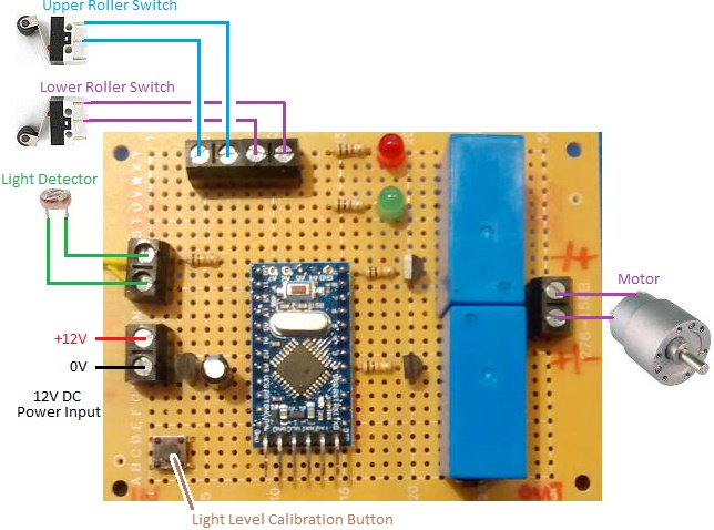
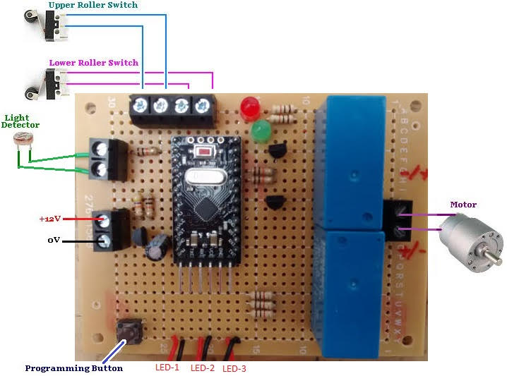
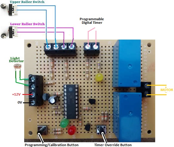
Pictured below is a new hen house door controller we recently made for a customer.hen house door controller with manual override
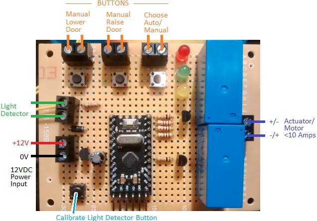
Our most common design for a door opener/closer is our Dawn Dusk Henhouse Door Controller – a device which uses a couple of roller limit switches to keep track of the position of the door, and a light detector to detect dawn and dusk.

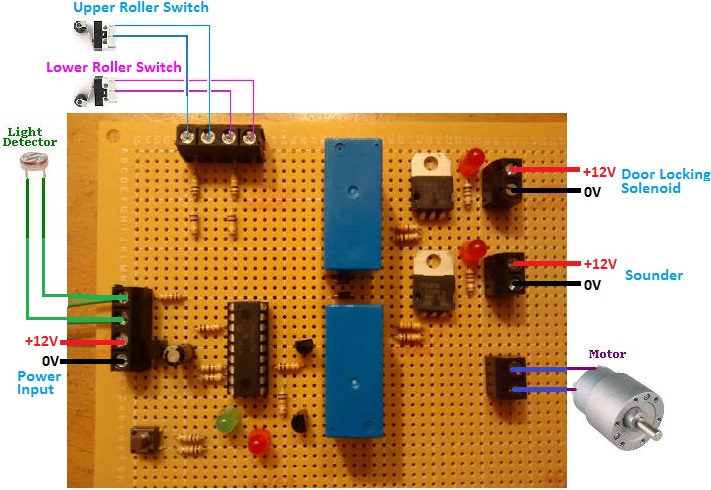
This new device is designed for operation with an aluminium screen door opened and closed by a linear actuator which has its own internal limit switches. At dawn, voltage is supplied to the actuator for one minute giving the actuator time to fully open the door with no worries that it will overrun thanks to the limit switches. At dusk, reverse polarity voltage is supplied to the actuator one one minute to close the door. The user can set the ambient light level threshold at which the door will open or close.

A further requirement for this controller was the ability to manually open or close the door at any time in order to give access to the chicken run. For this the user can select manual mode, and use the lower door or raise door buttons when they need to use the door. The controller keeps track of the position of the door during manual operation which is vital as there are no limit switches connected to the controller to tell it where the door is. On board buttons are available, but also screw in terminals so that external push-to-make buttons can be more conveniently located.

If you need any kind of door controller, please email neil@reuk.co.uk with details of your requirements.

Door Controller Instructions

Light Detector

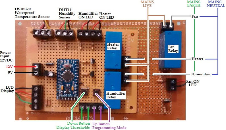
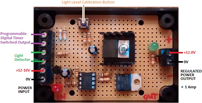
With the board connected up as per the diagram, the first step is to set the light detector threshold. The light detector is not waterproof, so it must be protected from rain, but also positioned so that it is exposed to natural light. The leads to the light detector can be extended to get it in an optimal safe location.

In the late afternoon / evening when the ambient light is at the level below which you want the door to be closed, press and hold the calibrate light detector button for more than one second. The red and green LEDs will then alternately flash for a few seconds and the current measured light level will be saved in memory as the night-dawn and day-dusk threshold.

Manual Operation

If the yellow LED is on, the device is in manual mode. To toggle between manual and automatic mode, press the choose auto/manual button.

In manual mode, pressing the manual lower door button will see power output to the actuator for one minute to close the door. (If during that one minute, you press the manual raise door button, power to the actuator will be cut leaving the door somewhere between open and closed.) Similarly, you can manually open the door by pressing the manual raise door button.

If you find that pressing the button to close the door instead opens the door, reverse the polarity of the power connections to the actuator.

Automatic Operation

When initially powered on, the device assumes that it is day time and the door is open. (If you connect the power at midday with the door closed for example, the door will not open until the following morning unless you manually open it.)

When it gets ‘dark’ – light level measured to be below the user set threshold – the red LED will turn on. After 10 seconds of continuous ‘darkness’, the door will automatically be closed with power supplied to the actuator for one minute and the actuator’s internal limit switches preventing the door from overrunning. Now the device will sleep for two hours – red and green LEDs alternately flashing – so that no false dawns are detected if the skies suddenly brighten.

After the sleep, it will now be very dark. The device will wait through the night until dawn – light level measured to be above the user set threshold – and then turn on the green LED. After 10 seconds of continuous ‘light’, the door will automatically open, again followed by a 2 hour sleep to prevent the detection of a false dusk if clouds cover the sun.

Poultry Egg Incubator with On Board Display and Humidity Maintenance

We have made many poultry egg incubators and timers over the last few years – devices which monitor and maintain temperature and humidity and also turn the eggs at regular intervals. Below is an image of one such incubator controller which we were recently commissioned to build which is a bit different from those.

poultry egg incubator controller

The motor is set to turn for three seconds five times per day to rotate the eggs. This is standard.

The heating element used for this incubator is a bit oversized, so we have to be careful not to overheat the eggs when it is used. When the temperature is measured to be 0.5C or more below a user set target temperature, the heater is turned on. Then, when the target temperature is reached, the heater is turned off. Because the element remains hot after being turned off, the incubator will continue to heat up to a little above target temperature while the element cools down. Therefore, there is also a fan which turns on just in case the temperature exceeds the target by 1.5C or more to cool things down long before the eggs overheat.

display for poultry egg incubation controller

Humidity management is also achieved rather differently than usual. In all previous incubators we have made which have included humidity sensing, a commercial humidifier has been switched on/off to maintain appropriate humidity levels. For this controller, when humidity is measured to be below a user set target minimum level, a pump is turned on for five second which adds water to a container in the incubator. The rapid evaporation of this water in the warmth of the incubator increases the humidity level back above the minimum rapidly. In order to prevent flooding or raising the humidity level excessively, the controller will run the pump at most once every ten minutes.

This entire system is powered by a solar charged 12V battery bank.

If you need any type of incubator (or humidor), please email neil@reuk.co.uk with details of your requirements.

Dawn Dusk Henhouse Door Controller Instructions

Pictured below is the connection diagram for the Arduino based standard REUK Dawn/Dusk Henhouse Door Controller. This device is sold as shown including the light detector (non-waterproof), but NOT including the rollers switches and motor which you must source yourself. We recommend the following:

Connection Diagram

connection diagram for Arduino based dawn dusk hen house door opener

Choosing a Motor

The choice of motor is particularly important. We favour the high torque low RPM type of motors linked to above because they are very strong, slow moving, and they do not draw a lot of current. Most importantly, if they are prevented from turning, they still draw well under 1 Amp. Other motors may draw only a couple of Amps in normal operation, but if the door becomes jammed (debris, snow, ice, motor or mechanism seizing, etc) then they can draw very high currents which exceed the 10 Amp rating of the components used on this controller. We suggest that a 5 Amp fuse is fitted in the positive line between the 12V battery (or power supply) and the positive Power Input of the controller.
You will have to double check which way the motor turns to open/close the door, and reverse the connections to it from the controller if the motor is turning the wrong way – i.e. trying to open the door at night, or close the door in the morning.

Roller Switches

For the roller switches, pretty much any will do the job electrically, so you just need to ensure that the ones you choose are sturdy enough to operate reliably with the door mechanism you have put together. The switches need to be wired to the controller such that the terminals are shorted out (closed) when the switch is closed, and are open when the switch is open. Most roller switches have three terminals – a COM (common), an NO (normally open), and an NC (normally closed). You need to use the COM (usually found in the centre), and the NO.

Setting the Light Level Threshold

You have one thing to set up – that is the light level threshold at which you consider it to be the point between day and dusk (and therefore the point between night and dawn). This calibration option is only available between connecting the power to the controller and it detecting dusk – i.e. during what it considers to be day time.
To calibrate the light level threshold, press and hold the Light Level Calibration Button. The red and green LEDs will both turn on. When they turn on (after around one second), release the button. Whatever is the measured light level by the light detector at this time will be stored in memory as the light level ‘threshold’. The red and green LEDs will rapidly flash for 10 seconds to let you know that calibration has been successfully completed. From now on, whenever the light level is brighter than this threshold it is ‘day’, and whenever the light level is darker than this threshold it is ‘night’. Obviously you need to go through this process at dusk when the ambient light level is the same as you want it to be when the door is to close. You need to have the light detector in the actual location and orientation it will have in operation.
The light detector is not waterproof and must therefore be protected from rain and also condensation. Ideally face it in a Southerly direction – if it is facing East or West then then ‘dawn’ will be detected late or early respectively.

Using the Door Controller

The controller starts off assuming that it is day time, so you want to start off with the door open. If the light level falls below the threshold you have set, the red LED will turn on. If the light level remains below the threshold continuously for 10 seconds, then the controller will assume that it is now dusk and will run the motor to close the door until the lower roller switch closes. The controller will then sleep for 2 hours to avoid a false dawn detection if the sun brightens up as it gets close to the horizon (as it often seems to do). During this time the red and green LEDs will blink so you know what is happening.
When the controller finishes sleeping, the ambient light level will be much lower (since it will be 2 hours further into the evening). The light detector will then wait until dawn. When the measured light level exceeds the threshold, the green LED will turn on. If the measured light level remains higher than the threshold continuously for 10 seconds, the controller will assume it is now dawn and run the motor to open the door until the upper roller switch closes. Again the controller will sleep for 2 hours to avoid false dusk detections.
This process will repeat every day.

Further Information

If you have any questions about the connection, setup, and use of this controller, email neil@reuk.co.uk.

Animal Feeder Motor Controller with Timer

Pictured below is a motor controller we made recently for an automatic animal feeder system.

Animal feeder motor controller with timerThe feeder itself has two buckets on a belt which is connected to a 12VDC motor. When the motor is run, the buckets scoop up feed from a container and drop it into a trough for the animals. If the motor is left running, more and more feed will be scooped up and added to the trough, so a controller was required to ensure that each time the motor was run, the correct amount of feed was deposited in the trough reliably.

The motor needs to run for less than one minute each time, therefore a 12V programmable digital timer was chosen. The user can programme the timer to turn ON for one minute at the exact times of day that the animals are to be fed.
A switch was added to the mechanical setup which closes each time the buckets have completed one full revolution – i.e. picked up and deposited feed.

The central controller waits for the timer to turn ON. Then it turns on the motor, and keeps it running until it detects the mechanical switch closing indicating that the feed buckets have been through one rotation.
When the timer next turns ON, the switch status is ignored for the first couple of seconds (since it remains closed until the motor has moved the buckets around a bit), and then the controller keeps the motor running until the switch closes again…another feed complete. This automatic feeder will keep the animals fed the right amount at the right times of day for as long as there is feed left to be scooped up.

If you need any kind of timer or motor controller, email neil@reuk.co.uk with details of your requirements.

Timer for Poultry Egg Incubator

Pictured below is a timer we built to accompany a Poultry Egg Incubator Controller we made recently.

timer for poultry egg incubatorWhen incubating eggs it is very important to keep track of the time since they were laid since, for example, eggs must be turned regularly until the last few days before hatching, and for some eggs the temperature and humidity ranges need minor adjustments during the incubation period.

Our timer is 12VDC powered like the incubator, and has a display to show the elapsed time since it was last manually reset. The time is shown in days:hours:minutes:seconds format.

Since eggs take anything up to 6 weeks to hatch, the time elapsed is stored in memory on the timer microcontroller every 15 minutes so that if the power to the timer is cut for any reason (e.g. flat battery or accidental disconnection of one of the power leads), when the timer is reconnected to power, it will restart from within no more than 15 minutes of where it was before the power cut.

After incubation has finished, a reset button (Reset Button 1) must be pressed for 1 second to reset the timer to 0:00:00:00 ready for the next lots of eggs to go into the incubator.resetting poultry egg incubator timer

This timer is built around an Arduino Pro Mini. The microcontroller with its on board crystal keeps time well enough for this application. (If more accuracy was required we would have added a real time clock (RTC).). Reset Button 2 on the timer resets the internal clock which is limited to 4,294,967,295 milliseconds (just under 50 days) – plenty of time for pretty much everything up to ostrich eggs, but not long enough for emperor penguin, albatross, and some cuckoo eggs. For exotic eggs with very long incubation periods, an RTC would need to be added.

If you need a timer or a poultry incubator controller, email neil@reuk.co.uk with details of your requirements.

Poultry Egg Incubator with Humidity Sensor

Pictured below is a controller we recently made for use in a poultry egg incubator, designed to keep eggs within a very narrow specific temperature and humidity range for a few weeks. This is achieved using a heater, a fan, and a humidifier.egg incubator with humidity sensor, fan, heater, and humidifierThe eggs need to be turned at least three times per day every day except for the last few days before hatching. Previously we made a Controller for Poultry Incubator which had a motor which was turned on and off at different times of the day to turn the eggs. For this new incubator, the motor used is a very slow turning 12 VAC device makes 6 full rotations every 24 hours. That motor therefore did not need to be controlled with a timer – it is just left running at all times.

egg incubator controller status summary displayThe display for this controller shows the current measured temperature from the waterproof DS18B20 digital temperature sensor (read at 12 bit resolution = 0.0625°C resolution), and the humidity from a DHT11 sensor (within 5% accuracy). The DHT11 actually has a built in thermistor, but its temperature measurements are nowhere nearly accurate enough for this type of project.

The bottom line of the display shows the three devices being controlled – heater, fan, and humidifier respectively. In the image above, the heater is marked as being on. If the humidity level gets too low, the humidifier will be switched on. If the temperature gets too hot, the fan will turn on (and of course the heater will already be turned off by then).

Setting humidity range for poultry egg incubator

The user has full control over the thresholds at which the heater, fan, and humidifier will turn on and turn off. The temperature thresholds for the heater and fan can be set in steps of 0.2°C, and the humidity thresholds in steps of 2%.

For example, the heater could be set to turn on at or below 36.4°C and off again at or above 38.4°C. Then the fan could be set to turn on at or above 38.6°C and off again at or below 37.4°C. Humidity should ideally be around 60% (raising to 65% just before hatching), so the humidifier could be set to turn on at or below 56% and off again at or above 64% relative humidity.

display for egg incubatorWith all the thresholds programmed in by the user according to the requirements of the particular type of eggs to be incubated, a button can be pressed to show in turn the values programmed in – for example, above the humidifier is shown to be set to turn on at or below 43% RH and turn off at or above 70% RH.

Feb 2020 – We have now released the full Arduino sketch (source code) for this device here: http://www.reuk.co.uk/wordpress/full-arduino-code-for-poultry-egg-incubator-with-humidity-sensor/

If you need any kind of egg incubator controller (or the electronics for a temperature and humidity controlled humidor – functionally pretty much identical to an incubator!) – please email neil@reuk.co.uk with details of your specific requirements.

Hen House Door Controller with Voltage Indication

Pictured below is another of our hen house door controllers – this time using a light detector to automatically detect dawn and dusk (user light level calibration), but with the addition of three battery voltage indicator LEDs.

Hen house door controller with low voltage indicationThis device will open and close a hen house door at dawn and dusk respectively when the measured ambient light level dictates. As this device is to be used with a small 12V battery, there is a chance that the battery will go low on charge preventing reliable operation.

Therefore we have added three LEDs (LED-1, LED-2 and LED-3) connected to flying leads so that they can be located somewhere easily visible while the controller itself is in an enclosure to keep it clean and dry.

When the battery voltage is measured to be greater than 12V, all three LEDs are turned on. When the voltage is between 11.8V and 12V, two are on. When the voltage is between 11.5 and 11.8V, 1 LED is on, and when the voltage is below 11.5V, no LEDs are on.

Each day when the user goes into the hen house to collect eggs, they have a quick visual indication of the state of the battery voltage so that they know when they need to think about recharging it.

If you need a hen house door controller, please email neil@reuk.co.uk with details of any specific requirements you may have.

hen house lighting controller with digital timer and light detector

Pictured below is a new hen house lighting controller we recently made.

hen house lighting controller with programmable digital timer and light detector overrideThis device is designed to controller artificial lighting in hen and other poultry housing to trick the birds into thinking it is summer even during the winter so that their egg yield is kept high throughout the year. It is based around our REUK Poultry Lighting System but with a few modifications.

This particular version makes use of both a light detector and a programmable digital timer. The user sets the timer to turn ON before dawn and turn OFF after dusk. During the hours of darkness between the timer turning ON and dawn, and then between dusk and timer turning OFF, the artificial lights are turned on. The output from this device passes through a low-drop 12V regulator to protect LED bulbs from excessive voltage.

With the timer turned ON for 15 hours per day (e.g. from 4am to 7pm), the level of light in the hen house will be optimised for the birds’ laying; and the light detector prevents the artificial lighting being on when not necessary (due to ambient lighting) which reduces the cost and size of the solar panel and battery used to power the system.

If you need any type of automatic poultry lighting or door opening controller, email neil@reuk.co.uk with details of your exact requirements.

Hen House Door Controller with Sounder and Door Locking Solenoid

Pictured below is another special order hen house door controller we have made on request. Our standard dawn/dusk door controller is detailed here: Automatic Dawn/Dusk Hen House Door Controller. For this customer we have added a couple of new features – a sounder/siren and a door locking solenoid.

Hen house door controller with sounder and door locking solenoidThe door is opened and closed automatically using a light detector and some microcontroller logic to determine when it is dawn and dusk respectively.

30 seconds before the door opens or closes and while the door is in motion, a sounder goes off which will hopefully train the birds to realise that the door is opening or closing so that they know what to do; and a solenoid door lock is used to ensure that the door is kept securely closed at night time (since in this particular case a full size shed door is being used instead of the usual drop down bird-sized door).

If you need any type of poultry house door controller, email neil@reuk.co.uk with details of your requirements.

Dawn Dusk Hen House Door Controller with Timer Override

Pictured below is a hen house door controller we recently made for a customer which is a modified version of our standard Dawn Dusk Hen House Door Controller.

hen house door controller with light detector and timer overrideThis controller will automatically open a hen house door at dawn and close it again at dusk. Dawn and dusk are detected via a light detector, and the user can calibrate the light level at which they consider it to be the transition between day and dusk and between night and dawn to meet their needs.

The modified version pictured above has the additional benefit of a programmable digital timer. We make hen house door controllers with light detectors which automatically detect dawn and dusk, and we also make them with programmable digital timers so that the user can instead set the exact time that the door is to open and close. This particular controller is our first which has both a light detector AND a programmable digital timer for maximum flexibility.

The purchaser of this controller expressed a wish to be able to have the hen house door close at dusk automatically, but also to be able (sometimes) to open the door later (or even earlier) than dawn. Therefore, in the summer when dawn could be at 4am, the timer can be used to keep the door closed until 6am or later to keep the noise down and avoid disturbing neighbours. The programmable digital timer we used can be set with different timings for weekdays and weekends, so for example, the door can be kept closed until much later in the morning on the weekend to keep the noise down.

If you need any kind of poultry door controller, email neil@reuk.co.uk with details of your exact requirements.