2x12V 24V Battery Bank Low Voltage Disconnect

24V battery bank low voltage disconnect LVD with dual battery measurement
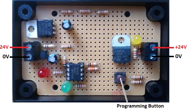
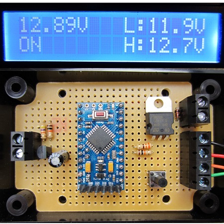
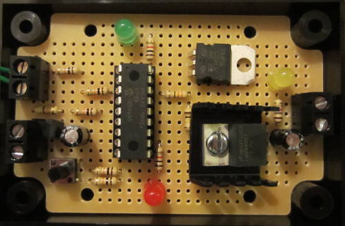
Pictured above is a low voltage disconnect (LVD) we recently made for use with a 24V battery bank comprising two 12V batteries. These two batteries do not equalise well (i.e. they do not hold the exact same charge or show the same voltage), and so this low voltage disconnect has to look at both batteries independently and take actions based upon the measurements of the weakest battery.

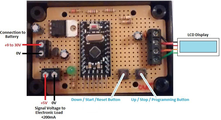
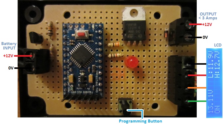
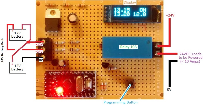
This device is based around our OLED display 12V LVD with some major modifications. The batteries are connected in series to make a 24V bank. The device measures the voltage of the whole battery bank and also measures the voltage of the first 12V battery. The second 12V battery voltage is then calculated by subtracting the first 12V battery voltage from the 24V battery bank voltage.

OLED display on 24V battery bank LVD
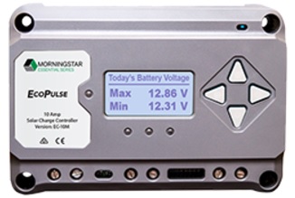
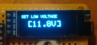
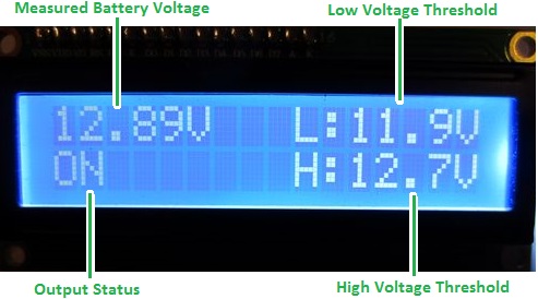
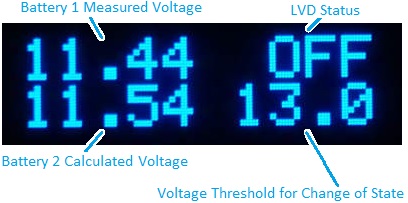
The OLED display on the low voltage disconnect shows the two battery voltages which make up the bank, the status of the LVD, and the voltage threshold (user programmable) at which the status of the LVD will next change (turn off the output if it is on, turn it on if it is off) depending on the charge level of the two batteries in the bank.

If the voltage of either battery in the battery bank falls below the low voltage threshold set by the user, the output will be turned off cutting the power to any devices being powered by the battery bank. When both of the batteries in the bank then reach a voltage in excess of the high voltage threshold set by the user, the output is restored reconnecting power to the devices powered by the battery bank.

If you need any kind of low voltage disconnect, please take a look at our range of LVD products, and email neil@reuk.co.uk if you have any special requirements.

24V Battery Charging Control Circuit

Pictured below is a 24V battery charging circuit which we recently made based around our more standard low voltage disconnects.

24V low voltage connect circuit for battery charging

Rather than a low voltage disconnect, this is a low voltage connect with the output used to control a relay which in turn connects a battery charger to the 24V battery bank. For this particular unit, the charger will be a hydraulic turbine generator, but everything would work the same if a plug-in battery charger was being used.

When the voltage from battery bank is measured to be below a user set value continuously for 10 seconds, the output turns on which starts battery charging. Charging continues until the battery bank is measured to be above a second (higher) user set value continuously for 10 seconds.

If you need any kind of low voltage disconnect/connect or anything to monitor an charge 12V or 24V batteries, email neil@reuk.co.uk with details of your requirements.

Morningstar EcoPulse PWM Solar Charge Controllers

Pictured below is one of the new range of EcoPulse solar charge controllers from Morningstar Corp (makers of the ever popular SunGuard Solar Controller). EcoPulse controllers are a part of the new Essential Series™ of consumer rated products designed for residential and off-grid use including the leisure market.morningstar ecopulse metered version

There are six different versions of the EcoPulse: 10A, 20A, and 30A rated with an interactive meter display as pictured above (EC-10M, EC-20M, and EC-30M), and 10A, 20A, and 30A rated with no display (EC-10, EC-20, and EC-30M) as pictured below.morningstar ecopulse non-metered version

EcoPulse controllers are designed for 12V and 24V solar systems with DIP switches used to select either 12V, 24V, or auto-detection.

These controllers are suitable for marine use as they are rated up to 100% humidity, the electronics have a protective conformal coating, and all connection terminals are corrosion resistant. The case is made from durable polycarbonate, and passive cooling is provided by an aluminium heatsink.morningstar ecopulse charging algorithmEcoPulse controllers have a 4-stage PWM battery charging algorithm – bulk charge, absorption, and float, with equalization available (automatic or disabled on non-metered models, manual or automatic on the metered models). The PWM frequency is 300Hz by default, but can be set to 1Hz if there is a problem with system noise.

EcoPulse has a built in adjustable dusk ‘til dawn lighting controller with the solar array being used as the ambient light detector.  (See our article Solar Panel as Darkness Detector for a simplified version of this technique.) A built in low voltage disconnect prevents the battery from being overly depleted by connected loads.

ecopulse pwm solar charge controller connection diagramEcoPulse has a built in sensor for temperature compensation, but an optional remote temperature sensor is also available if the controller is to be positioned more than 3 metres from the battery bank. There is also protection against short circuit, over current, and high voltage etc with fault indications displayed with coloured LEDs.

To find out more about EcoPulse, click here for the official Morningstar EcoPulse page where you will find links to the full operation manual and datasheet for the EcoPulse range.

The MSRP for the products in US Dollars are as follows and they are sold with a two-year manufacturers warranty:

  • EC-10 $65 EC-10M $101
  • EC-20 $78 EC-20M $129
  • EC-30 $104 EC-30M $156

Battery mAh Capactity Tester

low voltage disconnect with stopwatch for battery testingPictured above is a device we made recently to help estimate the capacity of 12V and 24V batteries. It is based loosely around our 12V Low Voltage Disconnect with Display, but with some major changes and functionality additions.

The customer for this device has a Farnell Electronic load which is capable of discharging batteries at up to 1.5kW (e.g. 12V @ 125A). He wanted to be able to use this to discharge batteries under test, to time accurately the discharge duration, and to automatically turn off the electronic load when the battery voltage falls below a user set level (for example 9.5V for a 12V battery).

This electronic load can be controlled externally by terminals on the back of the unit (Load Enable/Disable). If 5 VDC is connected across those terminals, the electronic load is enabled (turned on), otherwise it is disabled (turned off).

We therefore designed a device which the user can set with their choice of low voltage threshold. Then, when they press the Start Button, a regulated 5V is put across the terminals on the back of the electronic load which starts discharging the battery under test. At the same time, a stopwatch (created in software on the Arduino Pro Mini around which this controller is built) starts to display the number of days, hours, minutes, and seconds that have elapsed since the battery discharge began.

When the battery voltage is measured to have fallen below the low voltage threshold, the stopwatch stops, and the 5V signal to the electronic load is disconnected preventing the battery being discharged any further and potentially being permanently damaged.

The time on the stopwatch is saved in memory on our device and is displayed on the LCD until the user presses the reset button. It is saved in this way just in case after a multi-hour/day test has been completed, someone accidentally disconnects the battery from the timing device before noting the displayed timing results.

Pictured below is an alternative version of the same thing, designed for use with 12V batteries, and provided with an OLED display on board.

Device to time discharge of 12V battery to calculate mah capacity

This device works the same as the unit detailed above, but it has a smaller footprint, draws slightly less current from the battery itself, and it has a 1 Amp rated output to the electronic load @ 12VDC.

OLED display on battery mah capacity meter device

Pictured above is the display in standard operation showing the battery voltage at present, the low voltage threshold level (below which the electronic load will be switched off), and the running time so far.

Below shows the display when the device is in programming mode when the low voltage threshold can be set to a suitable value by the user.battery mah capacity meter low voltage disconnect

If you need any kind of voltage measuring device, low voltage disconnect, and/or timer, please email neil@reuk.co.uk with details of your exact requirements.

Low Voltage Disconnect used as Charge Controller

Pictured below is our 12V Programmable Low Voltage Disconnect with Display as sold in the REUK Shop. The product is designed to prevent batteries from being overly discharged and damaged by automatically turning the load devices on or off depending on the measured battery voltage.

reuk programmable low voltage disconnect used as a battery charge controllerWe recently made a few modifications to this design of this LVD for a customer to enable this device to be used as a charge controller; turning it into a high voltage disconnect.

There is a battery bank and a generator which is used to charge it. We replaced the standard 12V output on the low voltage disconnect board with a relay so that it could switch the generator on and off automatically. We then changed the code on the Arduino microcontroller so that the relay would open (turning off the generator) if the battery bank voltage exceeded a user set value, and would then close the relay again (turning on the generator) when the battery voltage fell below a second user set value. By doing this the batteries are well cared for – never being overcharged, and never becoming overly depleted.

If you require a low voltage disconnect or a modification made to one of our LVD products such as this charge controller, please email neil@reuk.co.uk with details of your requirements.

Programmable Low Voltage Automatic Battery Charger

Our Mini Programmable 12V Low Voltage Disconnect (LVD) is designed to disconnect loads from batteries when the battery voltage falls below  a user set value, and then reconnect the loads when the battery voltage gets back above a second (higher) user set value.

low voltage connect from REUK low voltage disconnectWith a few modifications to the code on the microcontroller of this device it can also be reconfigured as a low voltage connect – a device which will (typically) be used to connect a charger to the battery when its voltage gets low, and then disconnect it when the battery voltage gets higher after charging.

Today we made such a low voltage connect for a customer with a semi off grid garden office, a PV solar charged battery bank, and a selection of lights, 5V chargers, and other low voltage DC loads to be powered. He has a mains powered 5A bench power supply which he wanted to automatically connect to the battery bank via a solid state relay (SSR) when the battery bank voltage fell due to a period of poor solar generation (English weather) or from using a lot of battery power.

With our low voltage connect controlling the SSR, the battery bank will never be able to get overly-depleted and battery power will always be available to power the garden office.

If you need any kind of low voltage disconnect, low voltage connect, or high voltage disconnect etc, please email neil@reuk.co.uk with details of your requirements.

Poultry Lighting Controller with LVD and Display

We have been selling a selection of poultry lighting controllers for many years now – devices designed to stimulate egg production in the winter months using artificial light at dusk and/or before dawn to trick the birds.

Pictured below is a bespoke lighting controller we recently made for a more advanced poultry lighting controller including a double voltage regulator so that more LED bulbs can be used in a large poultry house, an automatic low voltage disconnect, and an LCD display to show system status and for use in setting up the system.

Poultry lighting controller with low voltage disconnect and display

This device will automatically detect dusk and turn on the lights in the poultry house for a user-programmable number of hours (including zero). The lights then turn off (if they had been on) and remain off for 9 hours to give the birds a 9 hour sleep and a 15 hour day for maximum egg production. The lights then turn on in the early morning and remain on until dawn when natural light is bright enough to take over.

display for poultry lighting controller with lvd

Dawn and dusk are detected using a light dependent resistor, and the user can calibrate the exact light level which they consider to be at the threshold between day and dusk, and between night and dawn.

To protect the battery from being run too low of charge and being damaged, the user can programme into the device three trigger voltages: a voltage below which the on board red LED will turn on as an early warning, a voltage below which the output (to the lights if on) will be turned off, and a voltage above which the low voltage disconnect will be cancelled restoring the outputs automatically when the battery is recharged.

manual override active on poultry lighting controller

There is also a manual override option which enables the lights to be turned on manually at any time (low voltage disconnect permitting) when the poultry house needs to be cleaned or the eggs to be collected etc.

At all times the backlit LCD display shows the status of the system including the currently measured battery voltage, whether the LVD is engaged, whether the outputs are on or off, the current position in the cycle DAY, DUSK, SLEEP, PREDAWN, DAWN (or MANUAL when the override is active), and the currently measured light level relative to the user set threshold.

If you need any kind of poultry lighting solution, please email neil@reuk.co.uk with details of your exact requirements and we should be able to put something suitable together for you.

Poultry Lighting Controller with Low Voltage Warning

We have been selling poultry lighting controllers for the last eight years designed to increase egg production during the long nights of winter. See here for details: Poultry Lighting Controllers.

Pictured below is a modified version of our standard Mark 3 lighting controller (sold here: REUK Super Poultry Lighting Controller) to which we have added a low battery voltage warning LED.

poultry lighting controller with built in low voltage warningThis modified version is designed primarily for use in lighting set ups where a solar panel is not used, and so the battery has to be charged by the user. When the battery voltage powering the controller and connected lighting falls below 12.0V, the red LED turns on to show the user that they need to recharge the battery as soon as possible to ensure reliable operation and battery longevity.

Contact neil@reuk.co.uk if you need any kind of poultry lighting controller with details of your exact requirements.

Low Voltage Disconnect with LCD Display

Pictured below is our latest low voltage disconnect circuit with LCD display.

REUK low voltage disconnect with LCD displayAs with our standard programmable low voltage disconnect (LVD), this device is designed to protect batteries from being discharged too deeply and permanently damaged. The user can set the low voltage at which the output loads will automatically be switched off, and also the higher cancellation voltage above which the output loads will be switched back on again.

LCD display on REUK low voltage disconnect (LVD)This particular LVD has a backlit LCD on which system information is constantly displayed. It is also used when setting the low and high voltage thresholds which makes things  a lot clearer and simpler than using LEDs or a rotary switch to programme those in.

As shown above the display shows the measured battery voltage updated multiple times per second and given to 2 decimal places of resolution (and calibrated to be accurate to within +/- 0.02 Volts across the range 10-16V).

The system status is usually ON or OFF, but can also be LOW or HIGH when the battery voltage is transitioning one of the thresholds about to change the state of the system. The high and low threshold voltages are also permanently displayed.

In order to avoid the output cycling on and off too often (particuarly as the battery voltages can spike or dip depending on the loads they are powering) there is a time delay during which the voltage must remain under/over the voltage threshold before the system will change from ON to OFF or OFF to ON respectively. During that time delay the backlight of the display flashes as a visual indicator that the threshold has been breached. We chose to flash the display itself rather than flashing an LED either on the board or on leads, since it is much easier to panel mount just the LCD than to mount both that and an LED indicator.

This particular client-tailored LVD has a MOSFET directly switching the output loads which can have a maximum total rating of 3 Amps. We can also make this with a relay fitted on board for direct switching, or a lower rated output which can be used to energise a high current (or high voltage) rated relay external to the board – e.g. an automotive relay or a solid state relay (SSR).

This low voltage voltage disconnect with LCD is now available direct from the REUK Shop. Click here to find out more or to purchase now: buy REUK Low Voltage Disconnect with LCD.

We will shortly be adding a very similar unit with the addition of datalogging functionality. Over the last couple of years we have sold many LVDs with built in dataloggers (see here for an example: Low Voltage Disconnect with Display and Datalogger), and we now have refined things to the point that the product is ready for general sale. In the meantime, if you have any requirement for a low voltage disconnect with or without a display and with or without datalogging, please email neil@reuk.co.uk with details of your requirements.

Arduino Datalogger Testing

We recently built and tested a very simple SD card datalogger based around an Arduino Pro Mini – the smallest and cheapest Arduino board commonly commercially available. We have previously described datalogging to an SD card with an Arduino in our blog post Arduino SD Card Datalogging (to log temperatures). In this example we are instead logging the voltage of a solar charged battery used to power the lights in a shed.

REUK Arduino Battery Voltage Datalogger

The Arduino Pro Mini (£3) was programmed from a PC via an FTDI breakout board (£5), and connected to an Arduino micro SD module (£1) fitted with a 1GB micro SD card (£3).  Note that the unlabelled components in the image above are not required for this datalogger – we just built the controller so that it can later also be used as a low voltage disconnect.

We programmed the Arduino to read in the voltage of a 5Ah 12V SLA (via a 47K-10K voltage divider) and write it to a log file on the SD card once every second. The battery is connected to an 80 Watt PV solar panel via a solar charge controller. The battery is also connected to  three 1W LED spotlight bulbs which were left permanently on so that the battery would drain over night and be recharged during the day.

The datalogger was left connected to the battery from around 10:30am one day to around noon the following day in mid-April with blue skies both days.

USB memory card reader

In order to view the data collected on the micro SD card we just needed a USB all-in-one memory card reader (£1). Plug the micro SD card into the reader, plug the reader into a PC via USB, and download the collected data.

The collected data file (which was simply a list of voltages measured to 2 decimal places) was 97070 lines long with a file size of 680 kB. Therefore our 1GB card could have logged the battery voltage once a second for 3-4 years.

Looking through the datalog in a text editor it was obvious that the battery voltage did not change very fast at all. Therefore logging the voltage every second was unnecessary for this application – every 30 seconds or every 60 seconds would have been adequate.

Knowing from experience that plotting 100,000+ data points with Excel is usually an unhappy experience, I first copied the log file over to my Raspberry Pi, and ran the following sed script to create a new smaller file containing just every 60th record from the log file. (This is equivalent to having set up the datalogger to log the voltage once per minute in the first place.)

sed -n '0~60p' logfile.txt > 60slogfile.txt

This command took just 0.24 seconds on the Raspberry Pi (thanks to the raw speed of sed) and I then dropped the new smaller (1617 records) log file into Excel and made the following plot of the results.

Datalogger data collected from solar powered shed lighting

The vertical axis shows the measured voltage, and the horizontal axis shows time with the far left being 10:30am on day1 and the far right being noon on day2.

The plot shows how the solar charge controller carries out a bulk charge phase to rapidly charge the battery (peaking at 14.6V) and then maintains a float charge (around 13.6V) during the day while the solar generation far exceeded the charge used by the spotlights. At night the voltage of the battery drops rapidly down hitting a low of 11.95V before the sun rose high enough to start to charge the battery again.

If you need a voltage datalogger like this, a voltage datalogger with a built in low voltage disconnect to protect the battery from being too deeply discharged, or any other kind of single or multi-channel datalogger, please email neil@reuk.co.uk with details of your exact requirements.