If you go to most supermarkets today you will see plug in mains powered digital programmable timers. These are designed to be used to automatically turn lights on and off, to turn washing machines on when you are out and so on. Prices start from as little as 5 pounds ($10) and these products are very feature rich often offering full seven-day programming and multiple on-off cycles per day.
Sadly these mass-produced units are only designed for mains powered devices. If you want to purchase a 12V Programmable Timer Switch you’ll find them to be feature-poor and very expensive (read linked-to article to find out more).
In our article Convert Thermostat to 12V Timer Switch we showed how a £20 battery powered timer thermostat could be converted easily to operate as a programmable timer relay switch. Unfortunately such a thermostat can be programmed with only one on-off cycle per day, and the shortest on (or off) interval it can provide is 15 minutes.
In this article we will show you how a cheap supermarket bought mains timer can be converted to operate on low voltage and control (i.e. switch on and off at programmed times) low voltage devices.
Convert Tesco TE7 7 Day Electronic Timer
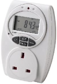
The timer pictured above is a TE7 7 Day Electronic Timer marketed within Tesco’s energy saving promotion and priced at just £8. This is the timer we will convert in this article.
NEW – After publishing this article, we discovered that the exact same timer is also sold by Sainsburys for around £8, but this time branded as Masterplug 7 Day Electronic Timer. With this branding it is also sold in the UK at Halfords, Woolworths, Focus DIY, and numerous other outlets.
The display on a programmable digital timer is not powered directly by mains electricity. Instead a small 1.2V NiMH rechargeable backup cell is kept charged, and the display and electronics are powered from that. This makes it perfect for our requirements.
When we took apart the TE7, the separation of the electronic timer from the mains electricity powered components was very simple since there are two completely separate circuit boards.
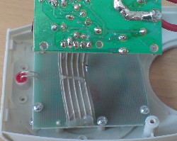
The two circuit boards are connected together by one ribbon cable comprising five insulated thin wires. Following the conductive copper lines printed on the circuit board we identified the ground connection and the NiMH cell (battery) positive connection immediately. A simple voltmeter was then used to test the voltage between the ground connection and each of the other three connections with the timer set manually to ON and then to OFF. We found that the middle connection goes high (1.2V = NiMH backup cell voltage) when the timer is ON, and low (0V) when the timer if OFF. That is all we needed to know.
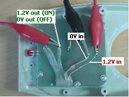
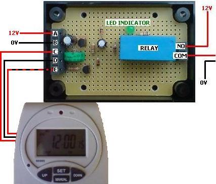
Now it is possible to discard (reuse or recycle!) the mains powered components simply by cutting through the ribbon cable as shown in the below labelled photograph:
This timer requires 1.2V to operate. Either a single AA cell can be used, or an LM317 can be set up to make a simple 1.25V Voltage Regulator if the finished system is to be powered from a larger battery.
Basic Relay Circuit
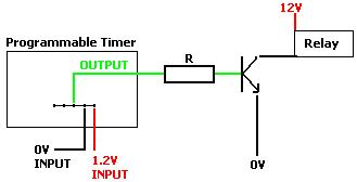
The simplest useful circuit possible with this timer is a relay controller. The 1.2V output which is present whenever the timer is ON can be passed through a transistor (via a current limiting resistor) to energise the coil of a relay. The relay can then be used to switch on and off irrigation systems, low voltage lighting, and a multitude of other devices and appliances following the settings programmed into the modified timer.
While prototyping this relay circuit we used a BC238B NPN transistor and a 1K resistor simply because those were the components we had to hand, however it would almost certainly have worked with any other NPN transistor with a current rating above that of the relay coil, and a 1K resistor.
Note that if the resistor is rated too high (e.g. 10K+), or if you use a darlington transistor, there will be atime lag between the timer starting to send the ON signal, and the relay switch closing – e.g. with a BC517 darlington transistor and a 10K resistor it takes up to 45 seconds for the relay to close after the timer goes ON.
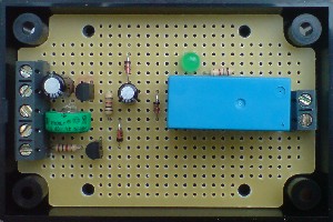
Pictured above is a circuit board with an integrated 1.25V regulator and relay controlled by the modified programmable timer. This board can be connected directly to a 12V battery or battery bank to turn low voltage devices on and off automatically.
Below is the full circuit diagram for this timer controller relay board.
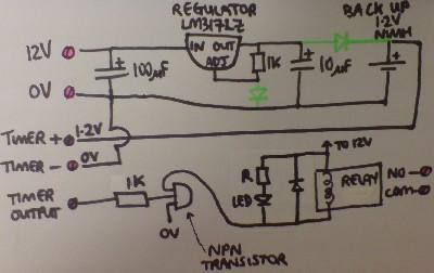
In this, the latest version of the circuit, the 1.2V NiMH rechargeable cell (desoldered from the mains powered circuit board) has been added so that the time and user entered ON/OFF programmes are not lost if/when the 12V power source is disconnected. We found that the actual measured output voltage from the LM317LZ was 1.32 Volts (with an input of 12.2V) and is therefore perfect to trickle charge the backup rechargeable cell at the same time as powering the timer.
This backup rechargeable cell will keep the timer running for over 100 hours after the 12V power source is disconnected.
Note the two diodes (coloured in green) on the circuit diagram – one between the regulator and the cell, and one between the regulator and 0V. The diode between the regulator and the cell prevents the cell draining charge back through the regulator. The diode between the regulator and 0V is there to cancel out the voltage dropped in the regulator-to-cell diode so that the cell and timer still see 1.2-1.3 Volts. Pretty much any type of diode can be used just as long as both are identical.
Many thanks to REUK.co.uk site visitor Gary for suggesting the inclusion of these diodes without which all programmed settings are lost within 1.5 seconds of the 12V power source being disconnected.
Buy a Modified Timer Relay
We are now selling these converted timers in the REUK Shop as a package with a 12V relay board with integrated voltage regulator (to power the timer). Click here for more information and to buy our Converted Programmable Digital Timer Relay now.
NEW – If you are interested in using this timer for winter poultry lighting, or if you intend to use it to power less than 5 Watts of LED spotlights, take a look at our new article REUK Poultry Lighting System. The controller described there should be perfect for your needs.