In our article Stepper Motor Basics we explain how a stepper motor can be used to generate electricityand how to use a multimeter to identify the wires which emerge from a stepper motor so that the AC voltage output can be rectified to DC voltage and used for battery charging or directly powering lighting and devices.
The most common type of stepper motor is a six-wire four-phase unit with four live AC outputs and twocommon outputs. In this article we will look at a small stepper motor of this type salvaged from a printer, identify the six wires, and from that build a picture of the inner workings of the stepper motor.
The Stepper Motor
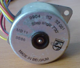
Our stepper motor is an old MB 11 sized Philips model with a 7 1/2 degree step angle. That means that it has 360/7.5 = 48 steps which means it would not be ideal for electricity generation and battery charging. As mentioned in our article Electricity with Stepper Motors it is best to choose a stepper motor with as many steps possible – usually 200 steps – since these motors generate higher voltages at lower rotation speeds; perfect for small DIY wind turbine generators.
Labelling the Wires
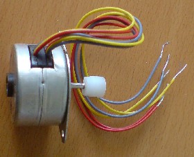
There are six wires emerging from this stepper motor: two red, two yellow, and two grey. One red, one grey, and one of the yellow wires have a dark mark on them, the other wires are clean. Therefore we can use those markings to individually identify the wires. If the wires all looked the same, then we would have individually labelled them with small pieces of tape. We will call the wires R1, Y1, G1, R2, Y2, and G2 where the letter is the first letter of the wire’s colour, and the number 1 or 2 identifies if the wire was clean (1) or marked (2).
Measuring Resistances
Systematically we connected the testing leads of the multimeter set to measure resistance to all possible combinations of pairs of wires coming out from the stepper motors. We put results we generated into the following table:
| R1 | R2 | G1 | G2 | Y1 | Y2 | |
| R1 | – | 117 | – | 117 | – | |
| R2 | – | – | 117 | – | 117 | |
| G1 | 117 | – | – | 234 | – | |
| G2 | – | 117 | – | – | 236 | |
| Y1 | 117 | – | 234 | – | – | |
| Y2 | – | 117 | – | 234 | – |
All of the above figures are measurements of resistance given in Ohms. Infinite resistance is represented by a ‘-‘.
Analysing the Stepper Motor Resistances
Where the resistance between two wires is infinite we know there is no connection between those two wires within the stepper motor – for example, between R1 and R2 or G1 and G2. We have two different values of resistance between the other wires – 117 Ohms and 234 Ohms with one being half of the other. This is because this stepper motor has four phases and therefore four identical coils. When the resistance measured between two wires is 117 Ohms, the wires are connected across one coil, and when the resistance is 234 Ohms the wires are connected across two coils.
Therefore we now know that R1 is connected to both G1 and to Y1 across one coil. R2 is connected to both G2 and to Y2 across one coil. G1 and Y1 are connected across two coils, and G2 and Y2 are connected across two coils. None of the 2’s are connected to any of the 1’s.
We can now use the information we have gleaned to draw the following simple diagram of the wiring within this stepper motor:
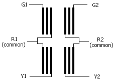
Our four live wires are therefore G1, G2, Y1, and Y2, and there are two common wires which must be R1 and R2. We now know everything we need to know to rectify the output from this small stepper motor into DC electricity for battery charging or to light some LEDs.
Although we carried out this process on a very small stepper motor, the exact same steps can be carried out on any size of stepper motor with any number of output wires to understand the internal wiring of the stepper motor so that it can be put to use as a generator.