In this article we will look at how a simple circuit can be built to act as a dimmer for individual LED bulbs. If you arrived at this page wanting to know how to dim LED spotlights (sealed bulbs containing multiple LEDs), you will be better served visiting this article 240V LED Bulbs and Dimmer Switches, Dimmable Energy Saving Lightbulbs, Lamina Sol MR16 LED Spotlight Review (dimmable), or this Review of Megaman Energy Saving Lightbulbs (CFL rather than LED, but currently the better type of low energy bulb for dimming).

LEDs (light emitting diodes) are very sensitive components – exceed their rated current or voltage and their lifespan can be slashed from 50,000+ hours to an eventful microsecond. LEDs are current-driven * which means that the intensity of the light they generate depends on the amount of electric current flowing them.
* The voltage drop across an LED depends entirely on the current flowing through it and ranges from 2-4 Volts for most LEDs.
Typically current is controlled using a resistor in series with the LED, or a current regulator circuit. Supplying more current to an LED increases its intensity, and reducing the current decreases its intensity. One way of dimming an LED is to use a variable resistor (potentiometer) to dynamically adjust the current getting to the LED and therefore increasing or decreasing its intensity. This works very well when just one LED bulb is involved.
Unfortunately, all LEDs are not made equal – even those of nominally identical specifications from the same batch from the same manufacturer. Although this will not be apparent when strings of LEDs are being driven with the recommended forward current (e.g. 25mA for ultrabright LEDs), as the current is reduced some LEDs will turn off before others, and some will be dim when others are still quite bright etc.
Pulse Width Modulation
A far superior method of dimming LEDs is to use Pulse Width Modulation (PWM). With PWM strings of LED bulbs can all be driven with the recommended forward current, with the dimming achieved by turning the LEDs on and off at high frequency – so fast the human eye cannot see the strobing effect. The longer the on periods are relative to the off periods, the brighter the LEDs will appear to the observer.
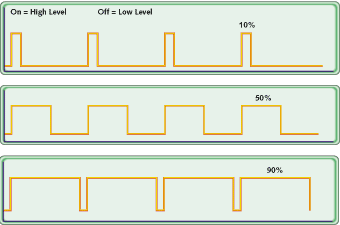
Duty Cycle is a percentage measure of the time that the LED is physically on. If, for example, the LED cycles ON for 9/1000 of a second, and then OFF for 1/1000 of a second, the duty cycle is 90%: 90% of the time it is ON, and 10% of the time it is OFF. Therefore, the intensity of the light will be approximately 90% of its undimmed level.
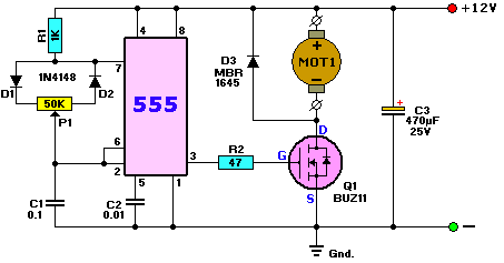
The easiest way to achieve this high frequency switching is to use a 555 timer integrated circuit (IC) – one of the commonest and most versatile ICs ever created. The circuit shown below (from the following article: Pulse Width Modulator with NE555 Timer Oscillator) is designed to be used as adimmer for 12V DC light bulbs or a speed controller for a 12V DC motor.
This circuit can easily be modified for use as dimmer circuit for LED bulbs powered from a 12V DC supply as shown below:
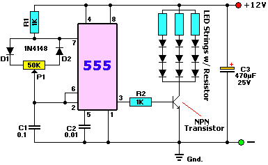
The NPN transistor selected must have an Ic rating in excess of the sum of the peak currents flowing through the strings of LEDs.
In our test circuit, the resistors in the LED strings were chosen to provide a forward current of 25mA to the LEDs. With three equal strings, the total current was 75mA and so we chose a transistor (BC547) with an Ic rating of 200mA – better safe than sorry.
This dimmer circuit cannot be used to turn the LEDs all the way off or to full brightness. In fact it operates within a duty cycle range of 5%-95% as the potentiometer (labelled P1) is turned from minimum to maximum. (By using germanium diodes in place of the two IN4148 signal diodes this dimming range can be extended to go from 1%-99%.)
PWM with a Microcontroller – LED Dimming with Arduino or PICAXE

While it is possible to build nice dimmers with simple components as shown above, for flexibility, speed, and ease of development, a microcontroller is often a better option. There are many different microcontrollers on the market which are very easy to programme, cheap to buy, and can be built into circuits with only a few external components required. They make it possible to very rapidly try out different things to see what works without having to make physical changes to the circuit board.
For microcontroller novices we typically recommend starting with PICAXE because of its simplicity, easy to learn programming language, prices, and good community. But for a beginner interested in PWM we would always recommend starting with Arduino. Although it is a bit more expensive and in general the programming language is a little more difficult to pick up, PWM specifically is very easy with Arduino and the ready made boards make experimentation and prototyping quick. Arduino also has an enormous community of users.
If you are using an Arduino board such as the commonly available Arduino Uno pictured above then there are multiple pins specifically designed for PWM output – for example, the pins labelled with a ~ on the Uno board (pins 3,5,6,9,10, and 11) are PWM-enabled which means you can use them to control the brightness of LEDs connected to them.
Below is a very simple circuit based around an Arduino Uno board which will dim or brighten a single red LED depending on the status of the connected potentiometer dial. When the dial of the potentiometer is turned all the way anti-clockwise, +5V will go into the Arduino analog input pin A0. When the potentiometer is turned all the way clockwise, 0V will go into A0. Between those two limits, the voltage going into A0 will be somewhere between 0 and +5V and proportional to how far the dial has been turned back from the clockwise limit.
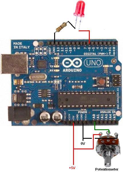
The Arduino will read in the 0-5V voltage from the potentiometer and convert it to a digital value from 0-1023. It can then use that value to set the brightness of the LED connected to PWM enabled digital pin 6 through a current limiting resistor with the following example code:
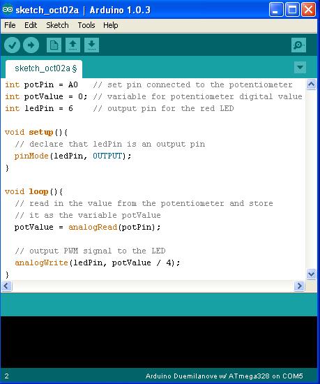
PWM with Arduino is achieved in this example using the call analogWrite(ledPin, XXX) where XXX is a number from 0-255 with 0 meaning 0% duty cycle, and 255 100% duty cycle. As the analogRead from the potentiometer input returns a value from 0-1023, in this ‘sketch’ we divide that value by 4 to get a value within the 0-255 range required.
With this circuit set up there are very many experiments you can try just be modifying the code uploaded to the Arduino – for example, the LED can be made to automatically fade and brighten with its rate of change set using the potentiometer.
When you become more experienced with Arduino, costs can be brought down by building Standalone Arduino Circuits with just the microcontroller and clock crystal on your own PCB or breadboard. However for rapid prototyping and experimentation the ready made complete boards cannot be beaten.
Using a Dimmer with 12V MR16 LED Spotlights
The circuit described above cannot be used with 12V MR16 LED spotlights of the type we sell in the REUK Shop. While individual LED bulbs are completely unharmed by being turned on and off rapidly, the internal circuitry of the spotlight unit does not appear to like it at all.
We connected one of our 12V LED spotlights to the dimmer circuit and found that some of the 20 LEDs in the unit flashed on and off, others turned off altogether, and others alternated between being very bright and very dim.