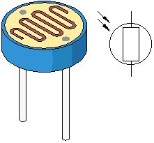
A Light Dependent Resistor (aka LDR, photoconductor, photoresistor, or photocell) is a component used commonly in electronics which has a resistance which decreases as the intensity of the light hitting its surface increases and visa versa. A typical light dependent resistor is pictured above together with (on the right hand side) its circuit diagram symbol.
The vast majority of LDRs are made from cadmium-sulphide (CdS), and they are very cheap, but also not very accurate. They are very good for detecting changes in light levels and determining if it is ‘dark’ or ‘light’, but without individual calibration they not suitable for accurately measuring light levels.
How Does a CdS Photocell Work
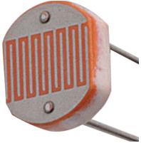
Pictured below is a typical light dependent resistor. It has two wire leads which terminate in the face of the light detector – the two metal dots you see are the ends of those electrodes. The main body of the light detector component is made of ceramic – an excellent insulator. On the face of the ceramic a thin strip of cadmium sulphide is coated in a zig-zag pattern (to maximise the length of the strip while keeping the component small) which is connected at each end to an electrode. The front face is then coated in clear plastic, epoxy, glass, or similar.
Cadmium-sulphide is a high resistance semiconductor, and is chosen for light detectors as it gives the same spectral response as the human eye – i.e. it ‘sees’/responds to the same range of wavelengths of light that we can see. Specifically, cadmium-sulphide is a photoconductive material. That means that photons of light hitting it with sufficient energy will release electrons from their atomic bonds.
When a negatively charged electron is freed by a photon of light, it leaves behind a positively charged ‘hole’. When a voltage is applied across the two wire leads of the light detector, the free electron moves one way along the CdS strip, and the free ‘hole’ moves the other way; and it is this movement of charge which is electricity flowing through the light detector. The higher the light intensity, the more photons of light are hitting the CdS strip, the more electron-hole pairs are generated, the more electricity can flow through the light detector, and so the lower the resistance of the light detector (i.e. it is easier for electricity to flow through the light detector when the light intensity hitting it is high).
Different LDR’s have different specifications, however the mini LDR‘s we sell in the REUK Shop are fairly standard and have a resistance in total darkness of 1 MOhm, and a resistance of a couple of hundred Ohm in bright light.
Uses for Light Dependent Resistors
Light dependent resistors are a vital component in any electric circuit which is to be turned on and off automatically according to the level of ambient light – for example, solar powered garden lights, and night security lighting.
An LDR can even be used in a simple remote control circuit using the backlight of a mobile phone to turn on a device – call the mobile from anywhere in the world, it lights up the LDR, and lighting (or agarden sprinkler) can be turned on remotely!
Light Dependent Resistor Circuits
There are two basic circuits using light dependent resistors – the first is activated by darkness, the second is activated by light. The two circuits are very similar and just require an LDR, some standardresistors, a variable resistor (aka potentiometer), and any small signal transistor.
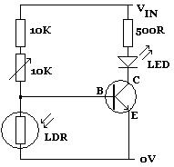
In the circuit diagram above, the LED lights up whenever the LDR is in darkness. The 10K variable resistor is used to fine-tune the level of darkness required before the LED lights up. The 10K standard resistor can be changed as required to achieve the desired effect, although any replacement must be at least 1K to protect the transistor from being damaged by excessive current.

By swapping the LDR over with the 10K and 10K variable resistors (as shown above), the circuit will be activated instead by light. Whenever sufficient light falls on the LDR (manually fine-tuned using the 10K variable resistor), the LED will light up.
Using an LDR in the Real World
The circuits shown above are not practically useful. In a real world circuit, the LED (and resistor) between the positive voltage input (Vin) and the collector (C) of the transistor would be replaced with the device to be powered.

Typically a relay is used – particularly when the low voltage light detecting circuit is used to switch on (or off) a 240V mains powered device. A diagram of that part of the circuit is shown above. When darkness falls (if the LDR circuit is configured that way around), the relay is triggered and the 240V device – for example a security light – switches on.
More Information and Products
For details of a more advanced light/dark sensor circuits click here to read our article LM741 Light/Dark Sensor Circuit. We have these circuits available for sale in both low current and high current(relay) switching versions as well as our Programmable REUK Dawn/Dusk Relay Controller.