Optocouplers
Optocouplers
Find out more about optocouplers/optoisolators and their uses
electronics | electric circuit | educationAn
optocoupler (aka
photocoupler or
opto-isolator) is an electronic component used to transfer a signal between different parts of a circuit which need to be electrically isolated from one another - for example, where a high voltage is to be switched with a low voltage signal. Typically in such situations a
relay is used, however these can be quite power hungry, prone to failure since they contain mechanical moving parts, and a relay is physically very large relative to the other components on a typical circuit board.
What is an Optocoupler
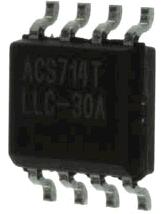
An
optocoupler uses light to transmit a signal and so two part of a circuit can be electrically isolatated. The image above shows a typical optocoupler - note that it is housed in a typical chip form and is therefore small and easy to mount on a circuit board.
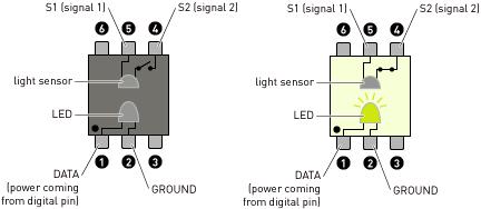
The schematics above depict the operation of an
optocoupler. The left hand image shows the switch which separates pins 4 and 5 on the chip is open since the
LED is not lit. The right hand image shows that switch now closed when the LED is lit. Pins 1 and 2 connect into one circuit, and pins 4 and 5 connect into a second circuit (electrically isolated) from the first. Note that the LED and light detector (
photo-transistor)
switch are all enclosed within the small optocoupler chip.
Example Optocoupler Circuit
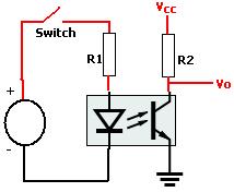
Above is an example of how an optocoupler is connected between the two isolated parts of a circuit - in this case acting as a logic NOT gate. When the switch is closed, the LED in the optocoupler lights up and that light is detected by the phototransistor in the optocoupler
. This pulls the output pin low - i.e. Vo is connected to ground via the phototransistor. When the switch is instead left open, Vo is instead connected to Vcc and so the output is high. Note the resistors R1 and R2 which are used to limit the current passed through the LED and the phototransistor.
Buy Optocouplers
A good selection of
optocouplers are available here:
buy Photocouplers, and here:
buy Optocouplers.
Article Last Modified: 12:33, 14th Aug 2010Comment on this Article
If you have any comments on this article, please email them to
neil@reuk.co.uk.
Recommended Related Articles
People who read this article also enjoyed the following articles:
Repeat Timer CircuitMake a repeat timer circuit with large intervals between ON times
Article Last Modified: 08:58, 15th Aug 2009electric circuit | electronics | generalTimer Circuits With 4060BBuild a reliable timer to switch devices on and off - from 30 seconds to 24 hours
Article Last Modified: 08:58, 15th Aug 2009electronics | electric circuitLED Dimmer CircuitFind out how to put together a simple but efficient PWM dimmer circuit for LEDs
Article Last Modified: 09:42, 16th Mar 2011lighting | electronics | electric circuitUsing The LM317T With LED LightingUse an LM317T to regulate the current in LED lighting projects
Article Last Modified: 12:47, 12th Mar 2008lighting | electric circuitLM741 Light Dark Sensor CircuitBuild a light/dark sensing circuit to automatically turn on/off lights and other devices
Article Last Modified: 08:43, 2nd Nov 2007electronics | electric circuit | generalLM317 Current CalculatorA handy online output current calculator for the LM317, LM338, and other linear voltage regulators
Article Last Modified: 12:47, 12th Mar 2008electric circuit | electronics | generalMaking Voltage Doublers and MultipliersFind out how to construct an AC voltage doubler circuit. Extend it to a tripler circuit and more.
Article Last Modified: 13:29, 26th Apr 2007electric circuit | education240V LED Bulbs and Dimmer SwitchesFind out more about 240V AC LED bulbs and dimmer switches
Article Last Modified: 15:12, 16th Jul 2007lightingDC Voltage Multiplier Circuit PlansBuild a circuit to boost the voltage of a DC power source using a MAX756
IC Chip
Article Last Modified: 14:10, 19th Nov 2010electric circuit | electronics | educationConvert Thermostat to 12v Timer SwitchFind out how to modify a battery powered thermostat to be used as a 12 Volt DC timer switch
Article Last Modified: 16:12, 24th Mar 2009electronics | electric circuit | general