With any circuit connected to a battery or other DC power source there is always the risk that you or someone will inadvertently connect it with reverse polarity – i.e. connect the positive from the power source to the negative input of the circuit and the negative from the power source to the positive input of the circuit. Depending on the circuit this will often cause a rapid destructive reaction with capacitors exploding, diodes burning out, transistors blowing etc.
In order to protect your circuits it is a good idea to incorporate some form of reverse polarity protection. In this article we will look at a few of the options available and discuss their relative merits.
Simple Reverse Polarity Protection – Series Diode
The simplest way to protect against reverse polarity connection is to incorporate a series diode just after where the positive DC connects to the circuit.
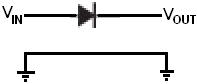
With this diode in series, current will only flow when the DC voltage is connected with the correct polarity.
The advantage of this technique is that it is very simple and cheap to implement. The disadvantage is that there is a voltage drop in the diode of 0.6V with a silicon diode (or 0.3V with a Schottky or germanium diode). For circuits drawing a high current, a lot of power will be lost as heat through the diode.
Bridge Rectifier for Reverse Polarity Protection
A second protection option is to use a Bridge Rectifier (otherwise known as a diode bridge) on the circuit input. This is a device made up of four diodes and more usually used to rectify (convert) AC voltage into DC voltage.
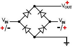
As shown above the two power source DC connections – one positive and one negative – connect to the AC input terminals (labelled ~) on the bridge rectifier. No matter which way around those two are connected, the connected circuit will receive the correct polarity DC. It is handy that the circuit will work no matter what the input polarity, but double the power and voltage is lost in the bridge rectifier than was the case with just the series diode because the current now has to pass through two diodes.
Zero Voltage Drop Reverse Polarity Protection
In both of the examples above a not inconsiderable amount of power is lost in the diode(s) protecting the circuit against reverse polarity. For circuits carrying high currents, a lot of heat would need to be dissipated, power wasted, and there is also the problem of the voltage drop to the circuit which may be too low after passing through the reverse polarity protection. What is often needed is a way to protect against reverse polarity connection, but which has zero voltage drop and no wasted power.
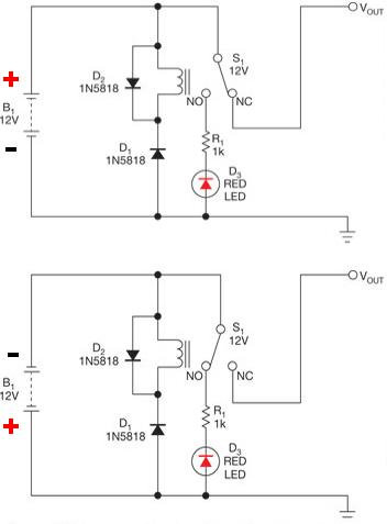
The circuit shown above (from EDN) uses a relay to protect against reverse polarity. When the correct polarity is used, the diode D1 blocks current from getting to the coil of the relay so it remains un-energised and so current can flow freely through the relay switch S1 to NC to Vout with no voltage drop or power loss.
If reverse polarity is connected, current can then flow through diode D1 and so the relay energises closing the switch S1. This results in the red LED turning on as a visual warning and the power to the system being interrupted to protect it from damage.