| RSS Web Feed for Renewable Energy UK |  | REUK Shop | Directory | Bookmark Site | About Us  

Simple Sump Pump Controller


Simple Sump Pump Controller

Put together a sump pump controller with two float switches and NO electronics

water | electric circuit | electronics
Printer Friendly Version Print Article     

Having a reliable system to pump out a sump pit is essential as mistakes and failures can lead to serious flooding and enormous expense. In our article Sump Pump Control System we introduced a selection of electronic solutions to the following problems:
1) Identifying when the sump pit is full and automatically turning on the pump.
2) Stopping the pump before the sump pit is empty so that the pump stays submerged (increasing its lifetime) and it never runs dry.
3) Not letting the pump turn on and off repeatedly (multiswitching) or excessively frequently.

One common comment from some of our site visitors is that they have very limited electronics knowledge and no soldering experience - therefore our sample circuit designs are no practical use to them. What they really want is a system which is foolproof to put together, requires no special tools or experience, and is easy to troubleshoot and maintain. In this article we will present a new sump pump control system which is economical and simple to build, very reliable, has few component parts, no electronics, and is easy to maintain.

Sump Pump Control System Design


Circuit design for float switch controlled sump pump controller

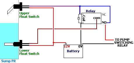
The system illustrated above is designed to work as follows: There are two float switches, one fixed high in the sump, and one positioned just above the height of the pump's water intake near the bottom of the sump. The upper float switch turns on the pump when the water reaches the high point. The lower float switch turns it off again when the water has been pumped out of the sump pit.

How Does the System Work

When the sump pit has water in it the lower float switch (LFS) is closed (i.e. floating horizontally). As the water level in the pit rises, it eventually reaches the upper float switch (UFS) lifting that float to the horizontal and closing its switch.

With the UFS closed, current flows from the 12V terminal of the battery to the relay coil energising it. This connects the COM and NO terminals of the relay allowing current to flow along a second path from the battery to the relay coil:

battery 12V -> LFS -> relay COM -> relay NO -> relay coil

Therefore, once the relay has been energised, it will latch - i.e. remain energised - as long as the LFS remains closed (which it will as long as it remains under water). As the pump empties the water from the sump pit, the pump stays on even when the UFS stops floating and until the water finally gets down to the level of the LFS. When the water level goes below the LFS, it breaks the connection between the relay coil and the 12V terminal of the battery, and so the relay switch will open turning off the pump.

Connecting the Pump

The output from the above described system comprises one 0V and one 12V connection. These are to be connected to the coil of a second relay which will physically switch the pump.
Connecting the pump to the float switch controlled system outputs
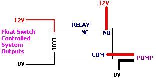
If it is a 12V pump you simply connect the COM of the second relay to the battery 12V terminal, the NO of the second relay to the pump's 12V connection, and the 0V terminal of the battery directly to the 0V connection of the pump.

If this is a mains powered pump the final connections must be made by a qualified electrician with everything insulated and earthed according to regulations. (The thick red lines in the above schematic correspond to the mains live, and the thick black lines to the mains neutral.)

Sump Pump Control Circuit Board

Pictured below is a small board put together following the main schematic shown at this beginning of this article. The only added component is an LED (with current limiting resistor) to give a visual indication of when the pump is on. With a board such as this it is possible to simply screw the float switches into the screw-in terminal connectors and keep everything tidy.

Float switch sump pump controller

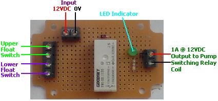
If you would like to have a board such as the one pictured above put together, please contact neil@reuk.co.uk with details of your exact requirements.

Further Uses for this System Design

This design is also useful in many irrigation, rainwater toilet flushing, and rainwater collection systems, particularly in remote locations where reliability and ease of maintenance are essential.
NEW - Click here to read our article Simple Well Pump Controller in which we modify this system so that it can be used to automatically fill (rather than empty) a tank.

Acknowledgements and Thanks

Many thanks to Nyge for his hard work and vital contributions to this new pump control system.
Article Last Modified: 08:58, 5th Aug 2008

Comment on this Article

If you have any comments on this article, please email them to neil@reuk.co.uk.


Recommended Related Articles

People who read this article also enjoyed the following articles:

Sump Pump Control System
Put together a fully automatic system to reliably pump out the water collected in a sump pit
Article Last Modified: 16:02, 2nd Jul 2008
water | electric circuit | electronics

Float Switch Water Level Measurement
Find out how to use float switches in renewable energy applications
Article Last Modified: 12:07, 28th Jul 2008
water | electric circuit

Resistor Colour Codes
Learn how to identify different resistors with their colour code
Article Last Modified: 14:19, 22nd Feb 2007
electric circuit | education

Simple Well Pump Controller
Find out how to automatically get water from the well into a header tank
Article Last Modified: 11:52, 1st Oct 2008
water | electronics | electric circuit

Using Breadboard to Make Circuits
Find out how a breadboard is used to design prototype electronic circuits
Article Last Modified: 12:52, 11th Apr 2009
electronics | education

Water Pump Hysteresis Circuit
A simple circuit to prevent a pump being damaged by being turned on and off rapidly (multiswitching)
Article Last Modified: 14:54, 19th Nov 2007
water | electronics | electric circuit

Timer Circuits With 4060B
Build a reliable timer to switch devices on and off - from 30 seconds to 24 hours
Article Last Modified: 09:58, 15th Aug 2009
electronics | electric circuit

Automatic Pump Shut Off Circuit
Put together an automatic system to switch off a pump when there is no more fluid left to pump
Article Last Modified: 14:54, 19th Nov 2007
water | electric circuit

Convert Digital Mains Timer To Low Voltage
Convert a cheap digital mains timer into a low voltage programmable timer relay
Article Last Modified: 10:21, 15th Nov 2008
electronics | electric circuit | general

Collect Rainwater
Don't waste the rain water that falls on your home. Use it.
Article Last Modified: 16:09, 1st Jun 2007
water

© 2006-2010 REUK - All Rights Reserved
Page Last Updated on 2nd September 2010 at 02:24:32pm

Latest
Articles


Eco Kettle 2 Chrome
Save electricity with an efficient eco kettle - new improved chrome version
energy efficiency
15:25, 18th Aug 2010

OWL CM119 Wireless Energy Monitor
Find out more about the new OWL CM119 wireless electricity monitor
shopping
15:23, 18th Aug 2010

KC7783R PIR Module
Find out more about the economical and easy to use KC7783R PIR motion sensor module
electronics
15:16, 18th Aug 2010

PIR Sensors
Find out how to integrate PIR (passive infra red) sensors into renewable energy applications
electronics
15:16, 18th Aug 2010

LM317 High Current Voltage Regulator
Find out how to build an LM317T based high current voltage regulator
electric circuit
12:29, 17th Aug 2010

LM317 Voltage Calculator
A handy online output voltage calculator for the LM317, LM338, and other linear voltage regulators
electric circuit
12:29, 17th Aug 2010

Optocouplers
Find out more about optocouplers/optoisolators and their uses
electronics
13:33, 14th Aug 2010

Relays and Renewable Energy
Find out more about relays and their uses in renewable energy applications
electric circuit
13:33, 14th Aug 2010


REUK Shop

Popular Items


REUK SUPER TIMER
User programmable 12V powered 10A rated repeating relay timer. 1 second to 99 hours ON and OFF times
£19.99 each.
Complete Circuits


SOLAR PUMP CONTROLLER WITH RELAY
Solar water heating system microprocessor controlled circuit with fitted 10A relay
£25.99 each.
Complete Circuits


12 VOLT 5 WATT SOLAR PANEL
Waterproof 12 Volt 5 Watt Solar Panel with aluminium frame - 290mm x 205mm x 17mm with fitted 5m leads
£33.99 each.
Solar Power


300 WATT POWER INVERTER
Convert 12V DC battery power into 230 AC to power portable televisions, computers, video recorders etc. 300 Watt power rating - peak power 600 Watts
£29.99 each.
Renewable Energy System Parts


CONVERTED PROGRAMMABLE DIGITAL TIMER RELAY
Mains powered programmable timer converted to low voltage with relay board
£21.99 each.
Renewable Energy System Parts


12 VOLT REGULATOR
Supply a fixed 12.0 Volt DC to your devices (up to 1 Amp output)
£4.99 each.
Complete Circuits


MR16 CERAMIC BULB HOLDER
Bulb holder for 12 Volt LED spotlight bulbs
£1.39 each.
Energy Efficient Lighting