In this article we will attempt to explain some of the basics of stepper motors and their use in renewable energy applications, primarily in basic Stepper Motor Wind Turbines with DIY PVC rotor blades.
If you want to read more in depth information about the workings of stepper motors then there are links to a selection of online resources at the bottom of this article.
Looking Inside Stepper Motors
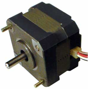
Inside a stepper motor are four coils of wire located 90 degrees away from each other – i.e. at positions 12, 3, 6, and 9 o’clock. In the middle is the rotor which spins and has permanent magnets fitted around its circumference. As the rotor spins each magnet in turn approaches, passes, and moves away from each of the four coils in turn. A magnet passing a coil of wire causes electricity to flow through that coil and so each of the four coils will have different amounts of electricity flowing through it either one way or the other – alternating current.
Since a stepper motor has four coils of wire, it is said to be a four-phase motor. (read more about three-phase electricity here to better understand multi-phase electricity). The advantage of this multi-phase set-up for electricity generation projects is that when one coil has no electricity flowing through it, the next coil will have reached its maximum. When the four-phases are brought together and rectified(more on rectification later) into direct current (DC), the total electricity generated therefore has a near constant voltage and current.
Stepper Motor Wiring
Most stepper motors have 6 wires, however there are motors with 4, 5, or 8 wires also. Each of the four coils is made up of one length of wire with two ends. One end is called live and the other end is called common. In a five-wire stepper motor all four commons are joined together, in a six-wire stepper motor two pairs of common wires are joined together, and in an eight-wire stepper motor none of the four common wires are joined together.
Identifying the Wires in a Stepper Motor
If you do not have a schematic diagram for your stepper motor – for example if it was salvaged from an old printer – it is usually relatively easy to work out which wire is which.
Systematically use a multimeter to measure the resistance between all possible combinations of pairs of wires. All four coils will have near identical resistances – if they did not the motor would not function properly. Therefore if the pair of wires being measured are both live, the resistance measured will be double that measured if one of the wires is a common. Why is this? Because two live wires have two coils between them whereas a common and a live have just one coil between them. (see diagram above)
When you have identified the common wires, be sure to label them.
NEW Click here to view our article on Examining a Stepper Motor in which we use the resistance between the different wires to work out which wire is which in a small 6-wire 4-phase stepper motor.
How to Rectify the Output from a Stepper Motor
Having identified the four live wires emerging from the stepper motor you now need to rectify the four-phase AC output into more useful direct current (DC) which can be used to power LEDs, charge batteries, and so on.
Basic Rectification with Diodes
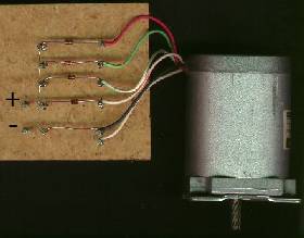
The simplest way to get started to to connect each of the four live wires to a diode, connecting the other ends of the four diodes together. This will act as the DC positive output, and the common wires when connected together (if there are more than one) act as the DC negative output.
An example of this is pictured above (image from the Campaign for Real Events Website). The positive pulses of AC electricity are added together and the negative pulses are completely blocked by the diodes in this half wave rectifier which of course results in the loss of half of the generated electricity!
Most stepper motors are labelled with their rated voltage and current per phase. Therefore the diodes used must be rated above (ideally at least double) the stated current per phase. (Standard 1N4001 1 Amp 50 Volt diodes are available from the REUK shop for a few pence each.)
nb. To reduce the amount of voltage dropped in the diodes, Germanium or Schottky diodes can be used instead of common silicon diodes. Schottky diodes are a little more expensive, and germanium diodes even more expensive, but they have a voltage drop per diode of around 0.3V typically compared to 0.6V for silicon diodes.
Rectifying with Bridge Rectifiers
To get a higher voltage, more current, and less wasted power, bridge rectifiers should be used. These will add together the magnitudes of the pulses of electricity, so +3V stays as +3V and -3V becomes +3V (minus losses in the diodes which make up the bridge rectifier). One bridge rectifier is required for each of the four phases with each of the live wires joined to the two AC (~) labelled legs of one bridge rectifier. The common wires of the stepper motor are not used. The positive output legs of the four bridge rectifiers are joined together to make the DC positive output and the negative legs of the bridge rectifiers are also joined together to make the DC negative output.
As with diodes, bridge rectifiers should be selected with spare capacity – for example, if the stepper motor is rated at 1 Amp per phase, 2 or 3 Amp rated bridge rectifiers at least should be used to prevent over-heating. In a bridge rectifier, the current flows through two diodes, and so the voltage drop is doubled to around 1.2V for typical silicon bridge rectifiers.
Bridge Rectifiers are available very cheaply – for example we sell 1.5 Amp, and 35 Amp bridge rectifiersin the REUK Shop, or you can very easily make a bridge rectifier with diodes if you are using a low current stepper motor. If you have a low voltage stepper motor, Schottky or germanium diodes can be used in your DIY bridge rectifier to minimise the dropped voltage.
The final component to add across the DC output is a Capacitor which is used in the circuit to smooth the output DC voltage from the bridge rectifier as it would otherwise fluctuate as the stepper motor rotates.
Further Reading
Here are some links to stepper motor resources online.
Stepper Motor Voltage Doubler Circuit – double the voltage of a stepper motor with a couple of bridge rectifiers and capacitors.
Identify the Wires of a Stepper Motor.
Wikipedia Stepper Motor article.
Stepper Motor Experiments.
Stepping Motors Resources.
Wind Generator from Old Scanner – Instructables guide to building a demonstration wind turbine using the stepper motor from an old flatbed scanner.
Stepper Motor Generator – generating 12V and 4W at 200 RPM with a size 34 – 14V stepper motor.