One problem we come across a lot is people wanting to control mains powered appliances using low voltage circuits – for example to power pumps for automatic irrigation systems, pumps for solar heating systems, and with our light detector, motion detector, and timer circuits. Usually we just supply a separate relay together with the circuit and suggest that a qualified electrician makes the high voltage connections and ensures everything is safely insulated and earthed according to regulations.
Thanks to the inventive mind of REUK site visitor Nyge this article will introduce a simple way to turn mains powered appliances on and off from the output from a low voltage battery powered circuit. No electronic components are required, and it is not necessary to go near any mains wiring.
Wireless Power Socket
The key component is one of those remote controlled power sockets such as Bye Bye Standby or Standby Buster. These devices have a wireless remote control which turns on a wireless mains power socket into which you can plug any mains powered device(s).
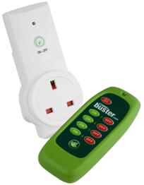
Pictured above is the Standby Buster. We chose this device as the RF remote control has a very sturdy circuit board (onto which we will need to solder a few wires), and the plastic case can be removed and replaced very easily. It is also one of the cheapest of these devices available – priced at just £14.95. (Click here to buy Standby Buster now)
Modifying the Standby Buster
On the back of the circuit board inside the Standby Buster are the contacts for the on and off buttons. If the two contacts for the ON or OFF buttons are connected – for example with a piece of wire – the circuit board thinks that you have pressed that button. Therefore, we need to solder one wire to each of the four contacts – two for each button as shown below.
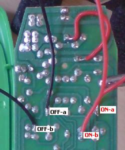
We used two red wires for the ON button and two black wires for the OFF button to make it easier to identify which wires correspond to which button later on. When the wires labelled ON-a and ON-b are touched together it is equivalent to pressing the ON button. When the wires labelled OFF-a and OFF-b are touched together it is equivalent to pressing the OFF button.
The Mains Switching Circuit
Pictured below is a schematic of the complete wireless mains power switching system. In addition to the Standby Buster already mentioned, two 3PDT relays are required. A 3PDT (three-pole double-throw) relay contains three switches each with a COM (common), NC (normally closed), and NO (normally open) connection. When such a relay is energised, each COM is connected to the corresponding NO; when the relay is not energised, each COM is connected to the corresponding NC.
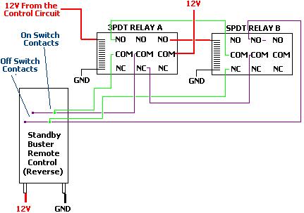
When the control circuit (light detector, motion detector etc) outputs 12VDC, it energises Relay A which in turn energises Relay B. Because relays do not switch instantly, there is a very short time lag between Relay A being energised and Relay B being energised. It is this time lag which is key to the system.
When the control circuit starts to send 12V to Relay A, there is a short time during which Relay A is energised but Relay B is not. During that time the ON button contacts are joined via the NO-COM of Relay A and the NC-COM of Relay B. When Relay B energises shortly afterwards, the NC-COM connection in Relay B is broken and so the connection between the two ON button contacts is also broken. Therefore we have reproduced the pressing of the ON button for <1/10 of a second – sufficient to fool the Standby Buster into turning on any appliance plugged into its power socket.
When the control circuit stops sending 12V to Relay A, Relay A de-energises a split second before Relay B. During the short time when Relay A is not energised, but Relay B still is, the two OFF button contacts are connected via the NC-COM of Relay A and the NO-COM of Relay B. When Relay-B de-energises, its NO-COM connection is broken and so is the connection between the OFF button contacts. Therefore this time we have reproduced pressing the OFF button on the Standby Buster turning off the appliance plugged into its power socket.
Any low voltage control circuit which was previously used to switch a relay can now be used to switch a mains powered device with the addition of two 3PDT relays and a Standby Buster. No mains wiring to do and no electrician required! As long as the mains powered device draws less than 13 Amps and it has (or could have) a standard plug fitted on it, it can be switched on and off automatically with this system.
Words of warning
This system should not be used for critical systems on the off chance a neighbour has a wireless device operating on the exact same frequency as your Standby Buster!