With very sharp turn-on characteristics, the TL431 is an excellent alternative to a zener diode in many applications. In this article we will look at how a TL431 can be used to make a very simple battery status monitor illuminating an LED when the input voltage is above a user set value.
Click here to view our article on making a battery status monitor with a zener diode.
Using the TL431
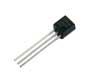
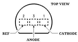
The TL431 is most commonly found in the TO-92 packaging pictured at the start of the article – a piece of black plastic out of which emerge three legs. Below the connections are labelled – REF is the voltage reference.
..and here below is shown the way the TL431 is represented in circuit diagrams

TL431s can be purchased cheaply from almost any stockist of electronic components worldwide. We also have them available for sale in the REUK Shop.
TL431 Voltage Monitor Circuit – Resistor Values
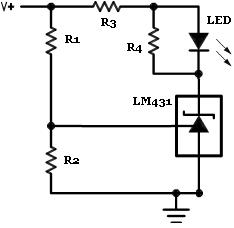
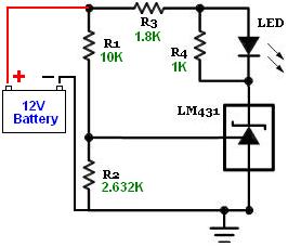
Above is shown the standard circuit diagram for a TL431-based voltage monitor. The aim of the monitor is simply to light up an LED when a target voltage is reached – perfect for a solar battery charger to let you know when the batteries have reached full charge.
The simple equation displayed above gives the high limit – in this case the voltage at which the LED will light up. Since the reference voltage (Vref) is fixed at 2.5 Volts in the TL431, the resistors R1 and R2 (which form a voltage divider) are selected to provide the desired high limit voltage.
If for example we fix R1=10K *, then with R2=1K we get a high limit of 27.5V, with R2=10K we get a high limit of 5V, and with R2=100K we get a high limit of 2.52V.
* Ideally the R1 and R2 resistors used should both be well over 1K Ohm to ensure that the reference input current stays below its 10mA safe use limit.
The high limit equation is more useful when rearranged so that we can calculate the required value of R2 for any chosen value of R1 and target high limit:
for example, if we chose R1 = 1.8K and we want an LED to light up when the input voltage reaches 7.0V:
so we would need a 1K resistor for R2 if R1 is 1.8K to get the LED to turn on at an input voltage of 7.0V.
The R3 resistor is there to protect the LED from excessive current with the value selected depends on the specification of the LED used, the brightness required, and the maximum likely input voltage. Typical values would be 470 Ohms for a 5-7V input, 1K to 1K8 for a 12V input etc.
The resistor labelled R4 in parallel with the LED prevents the LED from glowing softly when the input voltage is still below the switch-on voltage. We used a 1K Ohm resistor. (The lower the resistance value used for R4 for sharper the switch-on – i.e. a tiny increase in voltage over the high limit will cause the LED to suddenly light up brightly).
Testing the Voltage Tester
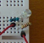
Below is a photograph of a TL431 voltage monitor put together on prototyping breadboard using the TL431 / LM431 to light up an LED when a voltage of 6.25V is reached.
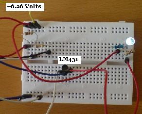
A 1K5 and a 1K resistor were used as R1 and R2 respectively to achieve the desired 6.25 Volt limit. A variable voltage source was then used to test the circuit. When the input voltage was 6.26 Volts the LED lit up (as shown above), and when the input voltage fell to 6.25 Volts the LED switched off completely (as shown below).
12V Battery Monitor with TL431
It is very important to monitor the voltage of the 12V battery or battery bank in a renewable energy system, so a 12V battery monitor is a useful tool to give a visual indication of the state of charge.
Let’s say we have a 12V battery bank, and we want a green LED to be on whenever the battery bank voltage is above 12.0V. Using the rearranged equation from above again we see that with R1=10K, and high limit = 12.0V, R2 is given by:
R2 = 10K / ((12.0 / 2.5) – 1) = 2.632K
In order to make this circuit more flexible, the 2.632K of R2 resistance can be replaced in part by a variable resistor so that the full range of useful low voltage warning values is available. For example, if you think you may want to be able to set the LED to come on at voltages from 10.5V to 12.5V for different applications, you would first calculate the value of R2 in each instance: for 10.5V R2=3.125K, and for 12.5V R2=2.5K.
You could then use 2.5K as the fixed R2 resistance connected in series to a 1K single-turn potentiometer for a voltage range of 9.64V to 12.5V which you would select by turning the potentiometer. Turn it all the way one way to make the LED come on at 12.5V, and turn it all the way the other way to make it come on at 9.64V. All the voltages in between those maximum and minimum values would be at different position of the potentiometer and can quickly be calibrated using a variable voltage source and a multimeter.
More Information
The full National Semiconductor LM431 Datasheet (PDF) can be viewed by clicking here. Note that the TL431 is also often labelled as a LM431 and may also be described as a programmable voltage reference.