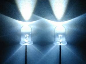
The lifetime of LED bulbs (now available in the REUK Shop) is strongly influenced by the amount of current passing through them. Though typically rated for 100,000 hours of use, if the current used is double that recommended the LED bulb lifetime can fall to 100 hours or less.
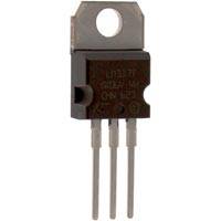
 It is therefore essential to regulate the current flowing through an LED circuit. This can be achieved using resistors however it is safer to use an LM317T chip as an adjustable current regulator.

Typically LED circuit current regulation is achieved by putting a resistor in series with the LED bulbs. (Read our article on making your own LED spotlights to find out more about selecting resistors for LED circuits.) Resistors are very cheaply available in an enormous range of sizes. However using resistors to regulate current in a circuit is not a very safe solution – particularly when the power supply used is not stable. A resistor in series with an LED may result in the exact desired current going through the LED at 12V, but at 15V that current could be much greater.
Problems Using Resistors to Regulate Current
If you wire three LEDs in series – each with a nominal current of 25ma (0.025 Amps) and a voltage drop of 3.6V – there is a total of 10.8 volts being dropped across the LEDs. If the power source is a 12 Volt battery then there is an additional 12-10.8=1.2V to drop to keep the LEDs happy.
Resistance is equal to voltage divided by current and so 1.2/0.025 = 48 Ohms is the size of resistor required. If a suitable resisitor (50 Ohms since that is the next manufactured resistor over 48 Ohms) is put in series with the LEDs then everything will work correctly – 25mA of current will flow through the LEDs in the circuit as desired and 0.03 Watts (1.2 volts * 25ma) will be dissipated as heat by the resistor.
However, in most renewable energy systems the voltage of the battery changes dramatically depending on the charging current. When the battery is not being charged it may give out only 12 Volts, but when it is being charged it can easily reach in excess of 14.5 Volts – particularly if a small battery is being charged by a large PV solar panel or wind turbine generator.
If the circuit described above has 14.5 Volts going through it rather than the 12 Volts for which it was designed then the extra voltage to be dropped is 14.5-10.8 = 3.7 Volts. This means a current of 3.7 Volts divided by 50 Ohms = 74ma would be passing through the LEDs (since all components connected in series receive the same current), enough to burn them out in a few hours.
Current Regulation with an LM317T
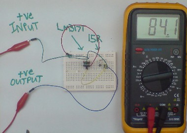
Getting a fixed current from power source using the LM317T is actually very easy. All that is required to fix the current is a resistor. The resistor is placed in series between the LM317T and the LED circuit, with the ADJ input of the LM317T connected to the circuit between the resistor and the LED circuit.
The LM317T always regulates the voltage on the ADJ input to 1.25 Volts – and therefore the current through the resisistor and therefore through the LED circuit will be constant. All we need to do is pick a resistor across which the nominal current of the LEDs will flow at 1.25 Volts using Ohm’s Law:
| Resistor Required (Ohms) = 1.25 (Volts) / nominal LED current (Amps) |
For example, with the white LEDs in the example given above had nominal currents of 0.025 Amps (25ma). Therefore we need a resisitor of 1.25/0.025 = 50 Ohms in our current regulation circuit. (The fact the resisistor needed in this circuit was the same value as the resistor in the example above was a coincidence!)
The power dissipated by the resistor is given by the regulated 1.25 Volts multiplied by the 25ma current = 0.03 Watts, so a standard 1/4 Watt resistor is more than sufficient to cope.
Click here to go to ourLM317 Current Calculator (pictured above). Simply enter your desired fixed output current, and the value and power rating of the required resistor will be displayed.
Don’t Forget the Volts Dropped in the LM317T
A couple of volts will be dropped in the LM317T and therefore the power supply required for the example above would have to be at least equal to the voltage drop across the LEDs (10.8V) plus 2 Volts = 12.8 Volts. Below this value the LEDs would not light – therefore the circuit would be better if it were modified to have two LEDs connected in series rather than three if a 12 Volt supply was to be used.
Limitations of the LM317T
The LM317T accepts an input voltage from 3 Volts to 40 Volts, and it will cope with an average current of 1.5 Amps. The higher the voltage and the higher the current, the hotter will get the LM317T – therefore a suitable TO-220 heatsink can become essential or the chip will automatically shut down and/or be damaged. Click here for our article on LM317 Heatsinking.
However these regulators are cheap and easily available if you make a mistake – and a burnt out LM317T is a lot less expensive than a string of of burnt out LEDs.
If you need more than 1.5 Amps of continuous current, consider the LM338T – a product which works in exactly the same way as the LM317T but with a continuous current rating of 5 Amps with suitable heatsinking.
Current Limited Solar Battery Charger
The current limiting circuit used here to safely light LEDs can be easily modified for use in a simple Solar Battery Charger. The resistor just needs to be changed so that the output current is around 10% of the capacity of the batteries to prevent overcharging.