PV Solar Panels have typical voltages of 3, 6, 12, 24 Volts etc. In this article we will look at how a simple electronic circuit can be built which will increase the voltage output from a small solar panel so it can be used to directly power a higher voltage device or to charge higher voltage batteries as an interesting project.
* For information on a voltage multiplier circuit which will boost the voltage from a source as low as 0.7V to either 3.3 or 5.0V using a MAX756 IC click here: 0.7V to 3.3/5.0V DC Converter.
The Voltage Doubler Circuit

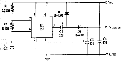
Pictured above is the voltage doubler circuit diagram. It is made from some very cheap and easy to source components, the key component being the NE555 timer IC – one of the most popular integrated circuits (ICs) of all time. In this circuit it is used to generate short pulses of DC electricity which are passed through a couple of diodes and capacitors which act to multiply the voltage. Click here to buyNE555 chips from just a few pence each.

The maximum output current of a 555 timer is typically 200 mA and it can dissipate up to 600mW of power – therefore this voltage doubler can only be used for low power devices and charging. Exceed the specifications and the chip may be destroyed. Click here for full typical NE555 Specifications (PDF) – in this case for the Texas Instruments NE555.
Also required are two 1N4002 diodes, 2 x 220uF and 1 x 470 uF electrolytic capacitors, 1 x 0.01uF (10nF) ceramic capacitor, and a 2.2k and a 15k resistor.
Connect Solar Panel to Voltage Doubler
The positive output from the solar panel is connected to the point labelled Vcc on the circuit diagram, and the negative output to the point labelled GND (ground).
The positive output from the circuit is taken from Vsource, and the ground from GND – for example, if using this circuit to charge a 9 Volt battery from a 6V solar panel, the positive terminal of the battery would be connected to Vsource, and the negative terminal of the battery to GND.
We have tested this exact circuit with a 6V 250mA solar panel and a 280mAh 9 Volt rechargeable battery. With a 6.25 Volt input from the solar panel, the output voltage was 9.70 Volts when just one LED (with 500 Ohm resistor) was used as a test load.
The efficiency of the DC-conversion was measured at only 50% – i.e. almost half of the collected solar energy was wasted in the circuit during the conversion process as heat.
Click here to find out more about Solar Battery Chargers.