A Transistor is an semiconductor which is a fundamental component in almost all electronic devices. Transistors are often said to be the most significant invention of the 20th Century. Transistors have many uses including switching, voltage/current regulation, and amplification – all of which are useful in renewable energy applications.
A transistor controls a large electrical output signal with changes to a small input signal. This is analogous to the small amount of effort required to open a tap (faucet) to release a large flow of water. Since a large amount of current can be controlled by a small amount of current, a transistor acts as an amplifier.
A transistor acts as a switch which can open and close many times per second.
Bipolar Junction Transistors
The most common type of transistor is a bipolar junction transistor. This is made up of three layers of a semi-conductor material in a sandwich. In one configuration the outer two layers have extra electrons, and the middle layer has electrons missing (holes). In the other configuration the two outer layers have the holes and the middle layer has the extra electrons.
Layers with extra electrons are called N-Type, those with electrons missing called P-Type. Therefore the bipolar junction transistors are more commonly known as PNP transistors and NPN transistors respectively.
Bipolar junction transistors are typically made of silicon and so they are very cheap to produce and purchase.
How do Transistors Work
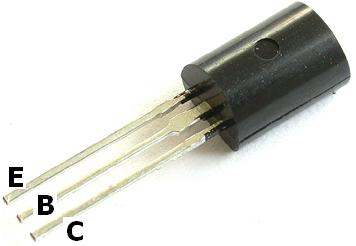
A bipolar junction transistor has three terminals – Base, Collector, and Emitter corresponding to the three semi-conductor layers of the transistor. The weak input current is applied to the inner (base) layer. When there is a small change in the current or voltage at the inner semiconductor layer (base), a rapid and far larger change in current takes place throughout the whole transistor.
Pictured above is a schematic diagram of the more common NPN transistor. Below is an illustration of the same transistor using water rather than electricity to illustrate the way it functions:
The illustration (from satcure-focus.com) shows pipework with three openings B (Base), C (Collector), and E (Emitter). The reservoir of water at C is the supply voltage which is prevented from getting though to E by a plunger. If water is poured into B, it pushes up the plunger letting lots of water flow from C to E. If even more water is poured into B, the plunger moves higher, and the flow of water from C to E increases.
Therefore, a small amount of water poured into B leads to a large volume of water flowing from C to E. Returning to electricity and transistors, a small input current of electricity to the Base leads to a large current flow of electricity from the Collector to the Emitter.
Transistor Gain
Looking at the water analogy again, if it takes 1 litre of water per minute poured into B to control 100 litres of water per minute flowing from C to E, then the Gain (or amplification factor) is 100. A real transistor with a gain of 100 can control 100mA of current from Collector to Emitter with an input current to the Base of just 1mA.
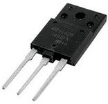
When a large amount of power (current × voltage) has to be switched, a power transistor is usually used. These are physically larger and stronger components designed to deal with heat dissipation – often with a hole to which an external heatsink can be attached. They require a larger controlling input current to the Base, while allowing much higher levels of current to flow through them.
Simple Transistor Circuit
Pictured above is a very simple circuit which demonstrates the use of transistors. When a finger is placed in the circuit where shown, a tiny current of around 0.1mA flows (assuming a finger resistance of 50,000 Ohms). This is nowhere near enough to light the LED which needs at least 10mA. However the tiny current is applied to the Base of the transistor where it is boosted by a factor (gain) of around 100 times and the LED lights!
Other Examples of Transistors Used in Circuits
Click here to view a worked example using a transistor to control LEDs.
We have many diverse circuits which utilise transistors illustrated and exaplined throughout the content on the REUK.co.uk website just a few of which are listed below to act as further worked examples:
LM741 Light Dark Sensor Circuit – turns a light on when it is dark outside.
LM317 Adjustable Power Supply – uses power transistors to increase the current output from an adjustable voltage power supply.
PIR Sensor Circuits – a selection of circuits for motion detection including a transistor inverter NOT gate.
LED Dimmer Circuit – for controlling LED bulbs with PWM.
Optocouplers – devices which act like transistors where electrical isolation is required between two parts of a circuit.