UK Home Energy Smart Meter Project Delayed

The installation of smart meters into all 30 million UK homes have been delayed by more than a year with the first meters unlikely to be installed until Autumn 2015, and all 30 million meters until 2020.

smart meters installation in the UK

The delays to the £11-12 billion project has been caused by industry needing more time for designing, building, and testing the systems which will enable the energy companies to communicate with the gas and electricity meters – for example to get daily accurate meter readings for all of their customers.

The huge costs of the project should be more than offset in the savings from not needing to employ people to read meters, and deal with customer complaints relating to estimated bills. Smart meters should help consumers understand their power usage and therefore take steps to reduce it.

EU to Impose High Import Duties on Chinese Made Solar Panels

In our article Are Prices of Solar Panels Going to Fall or Rise we looked at how Chinese-made PV solar panels have been flooding the European market driving prices down. Over the last few years, Chinese manufacturers have snapped up 80% of the $30bn+ annual European market for solar products.

The European Commission, interested in protecting German and other struggling European solar panel manufacturers, has been looking into this and are considering levying punitive tariffs on solar panel imports from China to stop Chinese manufacturers dumping their government subsidised panels in the European market at unfair prices.

Chinese made PV panels are currently almost half the price of European made panels and so the import duty is likely to be set at from 40-50% bringing Chinese and European panel prices in line with each other, and therefore increasing the price of solar products to the consumer considerably.

Provisional levies could come into force on 6th June 2013 before negotiations with Beijing on a long term levy structure. The USA put import duties on Chinese solar energy products back in 2012 to protect their market from oversupply.

Project of the Day – Swimming Pool Solar Water Heating Controller with Max Temperature

Today we have been working on a new solar water heating pump controller for use with a swimming pool with a user-settable maximum water temperature. This can be used to keep hot tubs at a safe temperature, or keep a swimming pool from getting unpleasantly hot.

This new device is based around our latest 2013 Solar Water Heating Pump Controller with the new features added on.

Swimming pool solar water heating controller with max temperature controlIn terms of hardware we have moved from a PICAXE-08M2 to a PICAXE-18M2 for its additional input/output pins, and then just added the yellow LED and second push button.

The operation of the controller is unchanged from the 2013 controller with the addition of the following functionality:

User can set maximum temperature the pool should reach to 1 degree accuracy from 25 degrees Celcius up.

If pool reaches the maximum temperature, the pump will turn off and not turn on again until the pool temperature has fallen by at least 2 degrees Celcius (hysteresis).

User can disable the maximum temperature feature or enable it with the push of a button.

If you need a controller of this type for your solar heated pool or hot-tub, do not hesitate to contact us via the REUK.co.uk website.

Multiple Buttons/Switches on one ADC Input

Small microcontrollers are cheap and easy to use, but one problem they have is a shortage of IO pins (input output). If you have a lot of inputs (e.g. sensors, switches, buttons etc), and outputs then a larger (more expensive) microcontroller is often required.

There is a good way around this problem when there are a lot of switches or buttons to detect; an example is shown below with three push to make buttons:

multiple switches connected to one microcontroller pin ADC

Instead of connecting the buttons to separate digital input pins on the microcontroller, each button can instead be connected up to different value resistor as shown above, and the combined output connected to an ADC (analogue digital converter) pin on the microcontroller.

When no buttons are being pressed, the ADC pin sees 0 volts thanks to the pull down resistor. If the top button is pressed, a voltage divider is formed with R1=47K and R2=10K, so the ADC pin sees 0.877V. If the middle button is pressed, a voltage divider is formed with R1=10K and R2=10K, so the ADC pin sees 2.500V. And if the bottom button is pressed, a voltage divider is formed with R1=1K and R2=10K, so the ADC pin sees 4.540V. The ADC pin monitors the voltage and by comparing the detected voltage with the known values for each button, the microcontroller will know which button has been pressed.

This is an excellent technique to use for up to around 10 buttons. Just remember that if more than one button is likely to be pressed at the same time things get a lot more complicated – particularly when there are a lot of buttons.

Standalone Arduino on a Breadboard

arduino duemilanove microcontroller board

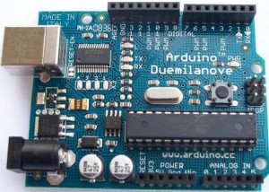
We have used Arduino boards in many of our projects. For those that do not know, Arduino is described as an open-source electronics prototyping platform and is basically a microcontroller on a preassembled board with a good selection of IO (inputs and outputs) and availability of shields (add-on circuit boards to help with internet connectivity, motor control, and much more) which can be connected. The boards have a USB socket through which code is downloaded to the board and also to enable control of devices via a PC.

Although Arduino boards are relatively cheap, starting from around £10 each (click here for best priced Arduino boards), things start to get expensive when you do multiple custom embedded projects – particularly when you are not using the majority of the features provided on the board.

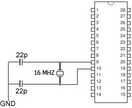
Fortunately it is possible to buy the microcontrollers which are found on the Arduino boards separately, add just a few components (a clock crystal, and a couple of capacitors), and build the rest of your project around that.

standalone arduino kit - microcontroller, crystal, and capacitors

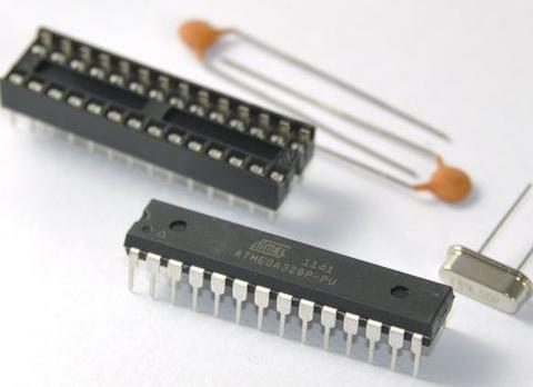
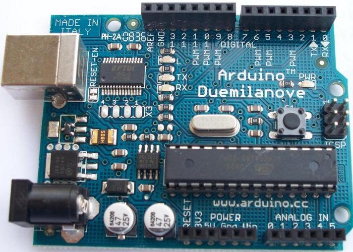
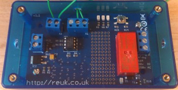
The common Arduino duemilanove board for example has an ATMEL ATmega 328 microcontroller which are easy to purchase BUT a blank microcontroller is not enough. It must have the correct Bootloader (software) on it before you can use it with the Arduino programming environment and USB connection. This is a job you can do yourself (with an ISP programmer), but for most people it will be much easier and cheaper just to purchase a kit such as the one pictured above which we use and available here for around £3 (Arduino Bootloader Kit). These have the bootloader pre-installed on the microcontroller and include a PCB socket, and the capacitors and the external 16MHz clock crystal.

Standalone Arduino circuit

Using these kits means you only need one Arduino board which you use to download your code sketches to the microcontroller. You then unplug the microcontroller from the Arduino board and plug it in on your own project board.

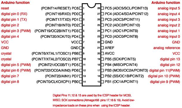
Below is the ATmega168 / ATmega328 Arduino pin mapping diagram so you know which pins on the microcontroller correspond to the inputs and outputs labelled on an Arduino board.

arduino atmega328 and atmega168 pin mapping

Project of the Day – Use Surplus PV with Air Source Heat Pump

Since the introduction of feed in tariffs in the UK we have been selling our REUK Solar PV Immersion Controller (pictured below) the concept of which is described in our article Water Heating with Surplus Solar PV.

REUK solar PV immersion controller

This device uses a light detector to estimate the level of solar electricity generation, and if it exceeds a user set threshold it switches on an immersion heating element so that electricity generated in excess of what is needed can be used to heat water rather than being exported (sold) to the Grid for just a few pence per unit.

An immersion heating element is a very simple resistive heater which can be turned on and off repeatedly during the day (with fluctuating levels of solar generation) without coming to any harm. If instead our standard controller is to be used to switch an air source heat pump (ASHP) or similar complex device then there could be problems.

One of our customers wanted to use our controller to power his air source heat pump with surplus PV solar generation, but in discussions with the manufacturer was told that the ASHP should be run for at least 30 minutes each time it is turned on. We therefore modified our controller software so that after the ASHP turns on (following a period of consistent good solar generation) it will stay on for 25 minutes, and then only turn off after a 5 minute period during which 90% of the light level readings show bad solar generation.

The result of these changes is that there will be times when the electricity demanded by the ASHP exceeds solar generation and so electricity will have to be imported (bought) from the Grid to meet the shortfall. But, as air source heat pumps cost thousands of pounds, it is much more important to protect the equipment from damage than to worry about the few extra pounds incurred in importing mains electricity.

Project of the Day – RC Helicopter Lighting Controller

Today we made a controller to turn on the navigation lights on a radio controlled helicopter when it is dusk or dark outside.

RC Helicopter lighting controller

Being a small RC helicopter, the lighting controller had to be small in size and low weight. A basic transistor circuit with light detector would not have been up to the job since the navigation lights would flicker on and off when the light detector was at the ambient light/dark threshold. The controller therefore needed hysteresis to avoid this multi-switching. It also needed to be easy for the user to set the light/dark threshold at which the navigation lights turn off/on.

To keep everything small, we used a PICAXE-08M2 microcontroller for this project. To set the light/dark threshold we decided against using a potentiometer in case vibrations from the helicopter’s motor caused it to rotate away from the user set position. Instead we fitted a small tactile switch to the circuit board. If this is pressed and held (at dusk) while the controller is being connected to the battery pack, the light detector (mini LDR) measures the current ambient light level and stores this in memory (not lost when battery disconnected) as the light/dark threshold.

In standard operation, when the light level is measured to be brighter than the threshold continuously for two seconds, the output to the navigation lights is turned on. If subsequently the light level is measured to be duller than the threshold continuously for two seconds, the output to the navigation lights is turned off.

The dimensions of the controller are under 2 x 2 inches.