In our article Low Voltage Battery Disconnect Circuits we explained how a low voltage disconnect (LVD) is a circuit designed to automatically disconnect loads from a battery when the battery voltage is low thereby protecting the battery from being damaged by being overly discharged.
While we sell user programmable low voltage disconnect circuits in our shop, we still receive many enquiries from people looking for a simple low voltage disconnect circuit which they can make for themselves. In this article we will show you how to do exactly this using very cheap and easy to source components.
NE555 Timer Low Voltage Disconnect
All we need to make a low voltage disconnect is something which can measure the voltage of the battery and connect the loads when the battery voltage is above a threshold and disconnect the loads when the battery voltage is below the threshold. But, we must include hysteresis to prevent the output flipping on and off rapidly when the battery voltage is at the threshold.
This can be achieved having one voltage threshold to disconnect the loads, and a different voltage threshold to connect the loads – e.g. disconnect the loads when the battery voltage is below 12.0V and reconnect them only when the battery voltage is above 12.4V. In order to achieve this all we need is one integrated circuit – the NE555 timer IC. This chip is used primarily to make timers and oscillators, but it can also operate as a bistable latch. The NE555 has two voltage comparators (trigger and threshold) which compare the voltage connected to them with the regulated NE555 supply voltage (Vcc).
When the voltage on the trigger input is less than 1/3 of Vcc, the NE555 output pin 3 goes and stays HIGH.
When the voltage on the threshold input is greater than 2/3 of Vcc, the NE555 output pin 3 goes and stays LOW.
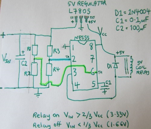
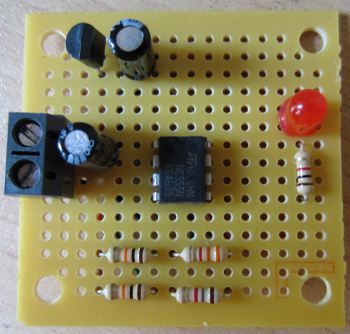
Above is the schematic for our low voltage disconnect based on the NE555 chip to which a couple of capacitors, an LM7805 voltage regulator, and a relay have been added. Last and most importantly we have two voltage dividers which will output a fixed fraction of the battery voltage to be measured.
(Capacitor C1 is there to prevent noise on the supply line affecting the voltage measurements etc, capacitor C2 helps to keep the voltage from the battery stable, and diode D1 is there to prevent back-EMF from the relay coil damaging the NE555.)
The LM7805 supplies a fixed 5V to the NE555 chip. Therefore the trigger input is waiting to respond to a voltage of less than 1/3 of 5V = 1.667V, and the threshold input is waiting to respond to a voltage of greater than 2/3 of 5V = 3.333V. So, we need to set the resistor values in the voltage dividers so that the trigger pin will see 1.667V when the battery voltage is at the voltage we want to engage the low voltage disconnect, and the threshold pin will see 3.333V when the battery voltage is at the voltage we want to cancel the low voltage disconnect.
Choosing Resistors for NE555 LVD Circuit
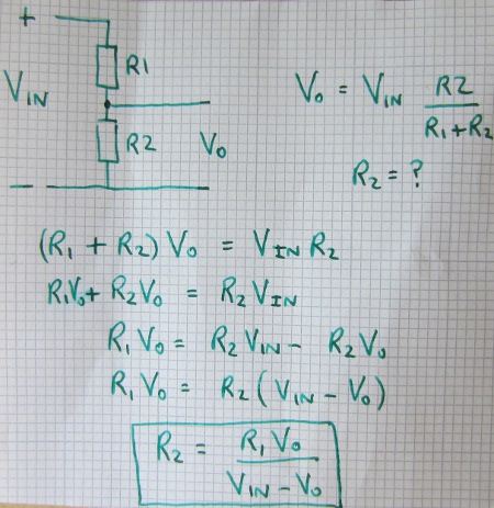
For simplicity set one of the resistors in each voltage divider to be 10K:
So, R1 = 10K, R3 = 10K.
All we need to do now is calculate the values of R2 and R4 which will give us the desired disconnect and reconnect voltages – in this example 11.8V and 12.8V respectively, but plug in your own values to meet your own requirements.
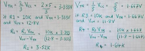
* VTH is the threshold voltage, and VTR is the trigger voltage.
In this example with 11.8V LVD and 12.8V cancellation of LVD we need 3.52K of resistor for R2, and 1.64K of resistor for R4.
LVD Circuit Operation
The output pin 3 on the NE555 will start off HIGH (+Vcc) so the relay will be open. When the battery voltage reaches 12.8V, the threshold pin will see 3.33V from the R1/R2 voltage divider and so the output pin will go LOW (0V). There will now be +5V across the relay coil and so it will close, connecting the loads to the battery.
Subsequently, when the battery voltage falls below 11.8V, the trigger pin will see 1.67V from the R3/R4 voltage divider and so the output pin will go HIGH (+Vcc). There will not be 0V across the relay coil and so it will open, disconnecting the loads from the battery.
Variable Voltage Low Voltage Disconnect
 To make a low voltage disconnect ciruit which does not have fixed voltages, you just need to replace some of R2 and R4 with potentiometers (variable resistance components). For example, if you wanted to have the flexibility to set the low voltage disconnect at anything from 11 to 12V, you need to find out which values of R4 cover that range. Putting the numbers in the equation, we find that R4=1.617K for disconnection at 12V, and R4=1.719 for disconnection at 11V. So, for R4 we need fixed resistance of 1.617K in series with a 0.1K (100 Ohm) potentiometer.