There are many affordable mains powered outdoor rated PIR sensors available, and many affordable low voltage indoor rated 12V Pir Sensors, but there are very few low voltage outdoor rated PIR sensorsavailable and those which are available tend to be quite expensive – typically 3x or more the price of mains powered units.
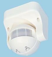
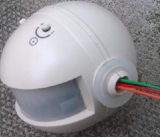
In this article we will look at how a good quality but low priced mains powered security motion sensorcan be easily modified for 12V DC operation with the addition of a few components and a little soldering. Our chosen PIR sensor is pictured above, and is available for sale here: ES34 External PIR Light Controller at less than £15.
This unit is supplied with all fixtures and fittings for external wall mounting, it is fitted with an internallight detector (user adjustable) so that the PIR can be used to trigger lighting only at night, it has a detection range of 12 metres over 180°, the angle of the PIR sensor can be adjusted, and there is space within the unit to add the necessary components to enable 12 Volt DC operation. The time the output is turned on for after motion is detected is user adjustable from 5 seconds to 12 minutes.
Converting the PIR Sensor
The unit is made up of the PIR sensor housed in a ball which is held by by arms attached to a case which contains the terminal strip to which the mains cables would normally be connected. Follow the instructions supplied with the unit to unscrew the back of the case to give access to the mains connections. Unscrew the three wires which are connected to the terminal strip and remove the terminal strip.
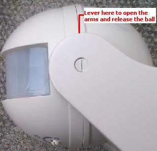
Now use a small flat headed screwdriver to lever the arm outwards (as shown above) so that the PIR ball is released from the case. Pull the cables which exit the PIR ball out from the case.
Pull out the two adjusters (LUX and time) from the ball and put them somewhere safe. It is easiest to lever them up with the small screwdriver and then pull them out with pliers or tweezers. (Note that if you rotate both of the adjusters all the way anti-clockwise before you remove them, it will help you get them back in the correct position later on.)
Using the same small screwdriver, split the ball in half pushing the screwdriver into the join between the two hemispheres on the opposite side from the opening through which the cables exit. With gentle pressure the ball will pop one revealing the electronics inside. There is a screw in the centre which holds everything in place. Remove this screw, and then release the circuit boards.
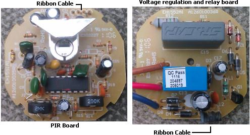
Pictured above are the two circuit boards. The one on the right contains the voltage regulation components which bring the mains voltage down to 24VDC, and a 24VDC relay. Unfortunately this relay cannot be energised by 12 Volts, and so this board will be discarded and replaced with a suitable 12V relay. The board on the left is the PIR board with the PIR sensor itself, user adjusters for LUX and time, and the microcontroller which manages everything. This is the board we will be keeping.
The two boards are connected by a ribbon cable. Cut this cable, cutting it all the way to the circuit board on the PIR board, and discard the other board.
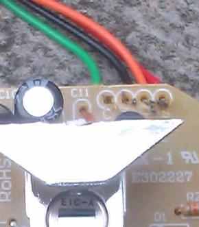
Four leads need to be soldered to the four terminals to which the ribbon cable was connected as shown above. To avoid confusion later on (and a destroyed PIR sensor) it is best to use a different colour for each lead.
Now clip the PIR sensor ball back together as shown above having first refitted the adjuster in the same positions they were before you dismantled the ball.
Using the colours we have used, we need to make the connections as follows:
green: connects directly to +ve of 12VDC supply.
black: connects directly to the -ve of 12VDC supply.
orange: connects to +ve of 12VDC supply via a 1K resistor.
red: connects to the base of a transistor via a 1K resistor.
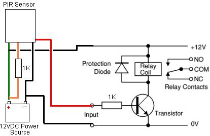
Everything ends up connected as per the circuit diagram above. Space is quite tight inside the PIR unit, so it is best to use a physically small relay and solder everything together as closely as possible. With that completed and tested squeeze the PIR ball back into place, screw the back of the case back on, and everything is ready to use with 12VDC.
Many thanks to Dave Hadden from Hadden Alarms for his help with this article:
Hadden Alarms have been trading in Aberdeen for 20 years. Our main areas are installing Alarm Systems, CCTV Systems, Access Control and repairs to these and associated products. We provide solutions to our customers requirements by combining various areas of expertise including the ability to interface different systems ie Alarms, CCTV, Lighting and phone signalling to work together. Many thanks to REUK, whose many circuit examples and projects are a regular source of reference for us.