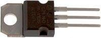
The LM317T is an adjustable voltage regulator chip in a TO-220 package (as pictured below). This chip can be used to supply a load current of up to 1.5 Amps at 1.2 to 37 Volts (from an input of 3 to 40 Volts).
The larger the output current, and the larger the difference between the input and desired output voltage, the greater the heat which will be dissipated by the chip during the voltage regulation process. This can cause the chip to heat up, and so a heatsink is often used to speed up heat removal and prevent overheating.
Calculate Power Dissipated by an LM317T Regulator
The power (heat) dissipated by an LM317T regulator can be calculated using the following simple formula:
where Vin is the input voltage, Vout is the output voltage,
and IL is the load current (measured in Amps).
For example, if an LED bulb rated at 3.3 Volts (and a current of 30mA) is to be powered from a 9V battery via an LM317T voltage regulator, the power dissipated will be (9V – 3.3V) * 0.030= 0.171 Watts.
Heatsinking an LM317T
An LM317T can safely be used to dissipate up to 0.25 Watts without any external heatsinking. Therefore in the example above with the LED powered by a 9V battery, the 0.171 Watts of heat dissipated would not require a heatsink.
However, if five such LED bulbs were to be powered (in parallel), the total current requirement would be 0.15A (=5 * 0.030A), and so the heat dissipated in the regulator would be 0.855 Watts. A heatsink would definitely be required or the regulator would overheat.
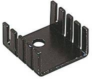
Heatsinks (such as the one pictured above, and sold here: bolt-on heatsink) have their thermal resistance specified – measured in degrees Celcius of heat rise per Watt of power dissipated. For example, the heatsink above has a thermal resistance of 21 degrees Celcius per Watt – i.e. if the regulator attached to it is dissipating a constant 1 Watt, the regulator will rise 21 degrees above ambient temperature. The better (larger and more efficient) a heatsink is, the lower the thermal resistance will be.
Typically you do not want a regulator chip to run at over 60 degrees Celcius. Therefore a heat sink should be chosen such that its thermal resistance will keep the temperature of the attached regulator below that maximum tolerable temperature. Therefore the maximum thermal resistance acceptable can be calculated according to the following formula:
For example in a room at a temperature of 20 degrees, a regulator dissipating 9 Watts of power would require a heatsink with a thermal resistance of less than (60 – 20) / 9 = 4.5 degrees per Watt.
Note that the absolute maximum dissipation rating for an LM317T is 15 Watts. If you need a voltage regulator which will dissipate more than that, consider the LM338. Alternatively have a read of our article LM317 High Current Voltage Regulator where we show you how adding a power transistor to an LM317 regulator circuit enables a high current voltage regulator to be built without overloading or overheating the LM317 IC itself.