At REUK.co.uk we are often asked to put together bespoke solar powered shed and garage lighting kits. Many of the components required are listed for sale in the REUK Shop, however many other necessary parts are also available with pricing on request. We prefer not to sell a standardised kit since everyone has his or her different requirements. If you would like solar powered lighting in your shed, garage, or outhouse, contact us and we will endeavour to be of assistance.
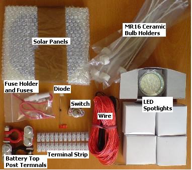
Pictured below is a typical solar shed lighting kit including everything bar a suitable deep cycle 12V leisure battery:
Solar Shed Lighting Kit
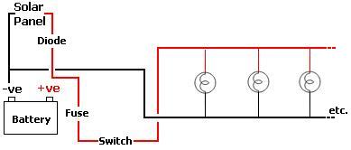
The basic circuit diagram is displayed on our solar shed lighting circuit testing page and is repeated below:
Making Connections Using Terminal Strip
Terminal strip enables secure connections between wires and components to be made quickly and easily with just a small flat head screwdriver required. For each connection cut off one piece of terminal strip with scissors or a knife.
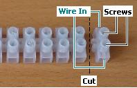
Wires (with the insulation stripped off the end) or other components to be connected are inserted into the holes labelled Wire In in the diagram above, and the screws tightened to hold them securely in place. Pull gently on each wire/component to ensure the connection is good.
Connecting Solar Panels Together
If you are using two or more 3V or 6V Solar Panels, they must first be joined in series. Line the solar panels up on a table connecting the postive lead from the first to the negative lead of the second and so on for each panel in turn.
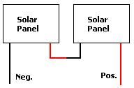
In the end the solar panels will all be connected to each other, with the negative lead from the first panel and the positive lead from the last panel free to be connected to the battery or battery bank. In the rest of this article, when the positive and negative lead of the solar panel are mentioned, we are referring to these two free leads (labelled above as Neg., and Pos.)
Connecting the Blocking Diode to the Solar Panel
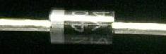
A blocking diode is usually used to allow electricity to flow from the solar panels into the batteries, but not from the batteries to radiate out from the solar panel at night. The diode should be connected to the positive lead from the solar panel to the battery with the stripe (ring) around the diode situated on the battery side.
Note that the diode will reduce the voltage sent to the batteries by the solar panels by as much as 0.7 Volts so you may choose to omit the diode from the circuit accepting small amounts of losses from the batteries in return for faster battery charging. For small 12V set-ups like this the diode is not really necessary and will almost certainly have an overall negative effect.
Connecting the Solar Panel to the Battery
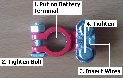
Ideally battery top post terminals should be used to connect wires to the battery. Some more information about them is available in our article on battery terminals. They are bolted securely onto the terminals of the battery, and any wires to be connected to the battery are in turn connected to them.
Warning – Protective goggles and gloves should always be work when handling batteries
Warning – While working on this lighting circuit, do not connect to the positive terminal of the battery until you are certain there is not a short-circuit – i.e. ensure there are no loose wires dangling about which could touch one another.
Using a Fuse
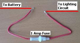
A suitable fuse should be used every time you draw power from a battery. If the terminals of the battery are accidentally short circuited the best you can hope for is some melted wire – the worst is a fire or acid-spraying battery explosion. The fuse should be connected into the positive wire from battery and as close to the battery as possible.
Connecting the Switch
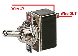
It is always better to include a switch in the lighting circuit rather than fiddling around with wires around the battery terminals to turn the lights on. The switch should be connected into the positive wire from the battery after the fuse. Position the switch so that it is easy to find in the dark.
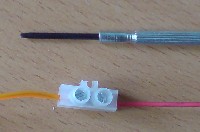
The Bulbs and MR16 Holders
Each MR16 Ceramic Bulb Holders should be fixed in its final location using a couple of screws or nails through the pre-drilled fixing holes. (Knowing exactly where each bulb will be located helps later on when cutting connecting lengths of wire.) A 12V LED Spotlight bulbs can then be plugged into each holder.
Wiring up the First Bulb
The final step in the process is to wire up the actual lighting circuit. Each MR16 bulb holder has two leads. Start off by connecting just one bulb, test everything is working okay, and then move on to extend the circuit as required.
Connect the leads of the first bulb holder in your circuit to the positive lead (after the switch) and to the negative lead from the battery.
* With the REUK LED bulb it does not matter which bulb holder lead connects to negative and which to positive.
Having checked that all connections are secure and that the light switch is in the OFF position, connect the circuit to the battery. When you switch ON the LED bulb should light up. If it does not, disconnect from the battery and check all connections have been made correctly, and that the fuse is good, and then try again.
Adding more Bulbs to the Circuit
Now you know that everything is working well in the circuit it is possible to add more bulbs. The REUK LED bulbs draw approximately 100mA of current, so using 1 Amp bell wire or similar and a 1 Amp fuse, 6 or 7 bulbs can safely be connected in parallel with one another.
Since a picture tells a thousand words, here’s how the bulbs are wired into a parallel chain:
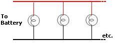
To achieve this (difficult to describe but easy to visualise) arrangement using terminal strip, it is best to first attach one piece of terminal strip to each of the leads of the remaining bulb holders to be connected. Then the wires arriving from the previous bulb, and those going on to the next bulb can be cut to size and wired in – two positive wires in one hole and two negative wires in the other hole. See below:
The last bulb in the circuit is connected to just two wires – the positive and the negative from the previous bulb.