While relays are very useful for switching things on and off, for situations where power consumption is to be kept to a minimum, the power used by the relay itself can be a problem – for example where a small LED light is to be switched, the power taken by the relay could be more than the power taken by the light. In a PV solar application this would result in a larger solar panel and larger battery being required which would increase costs.
One way around this is to use a latching relay – a relay which only takes power when it is in the process of changing state, but their use will usually require a complex circuit.
A feature of relays which is useful in this case is that the voltage required to hold a relay in the energised position (closed) is much lower than the voltage required to energise it in the first place. For example, a 12V relay will typically energise with a voltage of around 10.5V or more, but once energised will remain in that state as long as the voltage across the relay coil is maintained above as low as 3-5V. Since the resistance of the relay coil is fixed, reducing the voltage will reduce the current and power.
Reducing Relay Holding Current
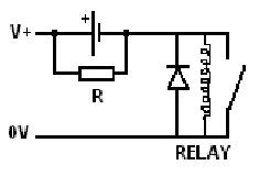
The schematic above shows how the holding current of a relay can be reduced with the addition of a capacitor and resistor. The capacitor needs to be quite large – typically a 1000uF capacitor is perfect. The value of the resistor R should be approximately double the rated resistance of the chosen relay coil to give a holding voltage of around one third of the supply voltage, but it is worth experimenting with a few different resistor values – the larger the value of R, the lower the current across the coil but the less reliably it will be held energised.
While the capacitor is filling with charge, the full supply voltage is across the relay coil and so the relay will energise as normal. Then as the capacitor reaches full charge, the voltage across the relay coil will fall to one third of the supply voltage – still sufficient to keep the relay energised.
The main risk with this simple solution is if the relay is vibrated or knocked violently enough that the relay jumps open. Then the one third of supply voltage will be no where near high enough to re-energise the relay. In most situations this will not be an issue, but automotive scenarios are one in which it should not be used.
Another issue to note is that the relay will de-energise at a much higher input voltage than before because the voltage actually getting to the relay coil is one third of what it would be if it were directly connected to the battery. For example, if a 12V battery is run down to 11V, a relay directly connected to it will remain energised – no problem. But, a relay which is connected via the capacitor and resistor as shown above may de-energise as the voltage it now receives is just 11/3 which could already be below the voltage threshold at which the relay cannot be held energised.
Testing
As a test we used a randomly selected Goodsky MI-SS-112L 12VDC coil relay. We measured the resistance of its coil to be 267 Ohms, so the current across the coil at 12.0V will be 45mA. Double 267 is 534, but a 470 Ohm rated resistor was the nearest value we had to hand (which we measured to actually be 460 Ohms).
Putting together the above shown circuit with a 25V rated 1000uF capacitor and the 460 Ohm resistor for R, the relay energised perfectly, and then the voltage across the coil settled down within a second to 4.31V. The relay remained energised, but the current across the coil had been reduced to just 16mA (a 65% reduction).
In further testing a 1K resistor was used for R resulting in a voltage across the coil of just 2.53V – less than 10mA and the relay remained energised until the supply voltage was turned down to 11V. For the best balance of efficiency and reliability therefore a resistor of around 600-700 Ohms would be ideal for this relay.
If this relay is to be held energised for 24 hours for example, then the difference between 16mA and 45mA is not insignificant. If the relay is powered with a 12V battery, it will take 1.1Ah from the battery @ 45mA in 24 hours, or just 0.4Ah @ 16mA over the same period. Therefore using the above simple capacitor and resistor solution can give real financial savings for solar charge battery systems since less solar charging and battery storage capacity is required as less power is being used.