There are many applications for which a timer is very useful to turn a device on or off automatically after a preset interval – for example, switching off an irrigation system after 30 minutes of use, turning off a battery charger to prevent overcharging, etc.
Timing short intervals of milliseconds to minutes can easily be achieved using a NE555 timer chip. Unfortunately, this device is not suitable for timing longer intervals, and so a suitable alternative is required.
Binary Counting with the 4060B

The 4060B (pictured above) is a CMOS binary counter. Using a resistor and a capacitor, the counting speed can be set by the user very easily. The pins of the 4060B integrated circuit output the running count in binary as shown below:
1 = 0000000001
2 = 0000000010
3 = 0000000011
4 = 0000000100
5 = 0000000101
6 = 0000000110
7 = 0000000111
8 = 0000001000
Each of the binary 1’s and 0’s is called a bit (much as the numbers 0,1,2…8,9 are called digits in the decimal number system). The furthest right bit represents 1, the next to the left represents 2, the next represents 4, the next 8, the next 16 and so on doubling every time you move one position to the left. Therefore 000010000 is binary for 16, and 000100000 is binary for 32.
To keep things simple, let’s assume the count is increased by one every second. The rightmost bit (the 1’s bit) will be off for one second, on for one second, off for one second and so on…
The fifth bit from the right (the 16’s bit) is therefore off for 16 seconds (when the count is 0-15), then on for 16 seconds (when the count is 16-31), then off for 16 seconds (when the count is 32-47), and so on.
With this knowledge, we can make a very accurate timer utilising our 4060B binary counter chip. Let’s say we want a 16 second timer: we start the 4060B counter from 0, and wait until the 16’s bit goes from 0 to 1. At that exact time we know that 16 seconds have elapsed. Similarly if we start the counter again, and wait until the 32’s bit goes from 0 to 1, we know that 32 seconds have elapsed.
A timer which can only time, 1, 2, 4, 8, 16, 32, 64, 128, and so on seconds would not be very useful, but since we can adjust the speed of the count, any time interval from seconds to 24+ hours can be accurately timed.
4060B Timer
A schematic of the 4060B chip is provided below:
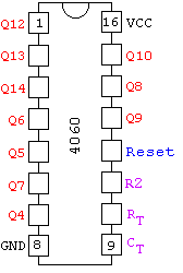
The pins labelled in red Q4-Q14 are the binary outputs: Q4 for the 16’s, Q5 for the 32’s, Q6 for the 64’s and so on up to Q13 for the 8192’s, and Q14 for the 16384’s.
Just three external components are required to control the 4060B counter – two resistors and one capactor. The frequency of the internal oscillator (i.e. the speed of the count) is set according to the equation given at the bottom of the schematic below:
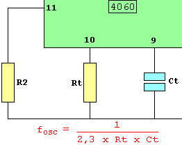
Since Q14 represents the 16,384’s and Q4 represents the 16’s – we know it will take 1,024 times longer (16,384 / 16) for Q14 to flip from 0 to 1 than it takes Q4. So, for an example 2-hour timer (=7,200 seconds), we just need to fine-tune the circuit so that Q4 turns on after 7,200 / 1,024 seconds = 7.03 seconds, knowing that if that is done correctly, after exactly 2 hours Q14 will flip from 0 to 1.
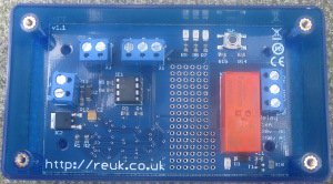
Putting Together the Timer Circuit
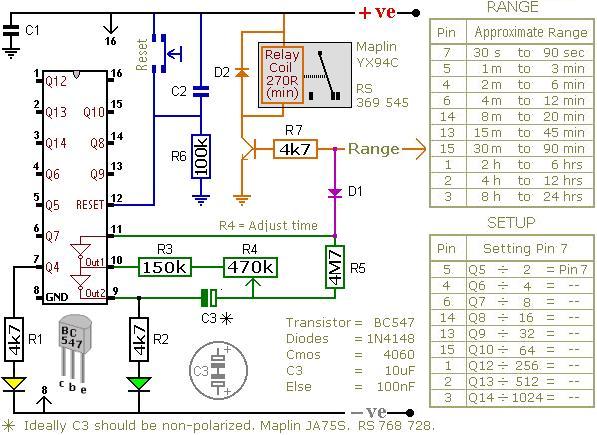
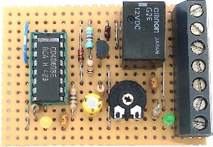
The circuit shown above (from Ron J’s Circuit Page) is a timer which energises a relay after a preset time has elapsed. It can be set to time an interval from 30 seconds to 24 hours.
The orange arrow labelled Range should be connected to a pin on the 4060B chip selected from theRANGE table. If for example, you require a timer to time 3 hours, connect it to pin number 1 on the chip since that pin corresponds to the time range 2hrs to 4hrs.
3 hours is 10,800 seconds, and we are using the output from pin 1 to trigger the relay. Looking at theSETUP table entry for pin 1 we see that we divide our target time (10,800 seconds) by 256 to obtain the on/off time for the yellow LED at pin 7 = 42.28 seconds. Therefore, if we adjust the potentiometer R4so that the yellow LED turns on after approximately 42 seconds, we’ll know that the relay will be energised after approximately 3 hours.
The diode D1 makes this a one-shot timer. This means that after the programmed time delay of 3 hours, the relay will stay on until the circuit is reset. If the diode is omitted from the circuit then you get a repeating timer with the relay off for 3 hours, on for 3 hours, off for 3 hours, and so on until the circuit it reset.
To build a repeat timer with different ON/OFF durations based around the 4060B – for example, 1 hour OFF, 1 minute ON, 1 hour OFF, 1 minute ON etc – click here to read our article Repeat Timer Circuit.
Microcontrollers for Timers
We originally published this article back in 2006. Since then there has been a huge growth in the popularity of microcontrollers suitable for use by makers – for example PICAXE and Arduino, as well as the introduction of the Raspberry Pi.
Using microcontrollers enables complex devices to be made with minimal electronic components and soldering – the complexity is hidden away in the software you write and load onto the microcontroller. This makes it much faster and easier to prototype and make changes to your project.
Click here for our automatic PICAXE code generator for a repeating timer: Make a PICAXE Repeating Timer. All you need to do is put together the PICAXE prototype board, download the generated code to the microcontroller chip, and you will have a reliable repeating timer which you can easily re-programme as and when required without needing to get out your soldering iron again.
Buy a Timer Circuit
If you need a timer circuit for any application, email neil@reuk.co.uk with details of your exact requirements and we’ll happily put together a bespoke solution.
If you just need a general user-programmable repeating relay timer, then click here for details on ourREUK Super Timer and REUK Super Timer 2 (pictured above). These are our popular fully built repeating relay timers which you can simply programme with independent ON and OFF durations from 1 second to 99 hours using a button.