In our articles Float Switch Water Level Measurement and Automatic Pump Shut Off Circuit we looked at simple ways of controlling a pump automatically according to the level of water in a tank.
We mentioned in the second of those articles that a pump can be destroyed if it is run dry – i.e. when it is run when there is no water to pump. Another way to reduce the life of a pump (and also to waste power) is to switch it on and off rapidly (multiswitching). For the first few seconds after a pump is started, a lot of power (up to three times the power used when it is up and running) is necessary and this strains the components in the pump each time it is started up.
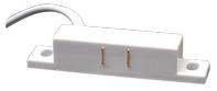
When using a Float Switch or Liquid sensor there is always the risk that turbulence in the water (caused by the container being moved or by water being pumped into it) will cause the sensor to turn on and off rapidly as the water sloshes about. If the sensor is used directly (with or without a relay) to control a pump, then the pump will also turn on and off rapidly. In this article we will look at a circuit which provides a time delay between the threshold water level being reached and the pump being activated.
Time Delay Pump Controller
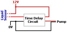
This circuit is designed to operate very simply. When the water reaches the level necessary to trigger the high level float switch or liquid sensor, a timer is started. If during the following 10 seconds the switch/sensor does not open, a relay will be energised which will in turn connect power to the pump turning it on. Therefore this controller is designed for a system which automatically empties a sump pit for example (see our article Simple Sump Pump Controller for an alternative two float switch design requiring no electronics).
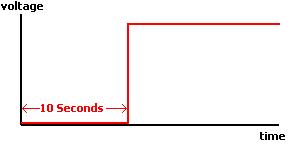
When the switch/sensor opens (i.e. when the water level falls below the preset value even for a split second) the 10 second delay timer will start again from zero. Therefore, it the pump will not toggle on and off rapidly because it will only turn on after 10 continuous seconds of the float switch being closed – i.e. long after any turbulence has stabilised.
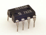
To achieve the desired result an NE555 integrated circuit (IC) can be used as a timer. This IC (click here for full NE555 Specifications) can output up to 200mA of current – easily enough to energise the coil of a typical 12 Volt relay. The technical desciption of its use in this application is monostable operation delay on – i.e. after a delay, the IC will output a continuous positive current until the power to it is cut. In order to get the pump to switch off again once it is running, a second float switch or liquid sensor, or a second timer can be used. In our design below we have used a second float switch. (See our article Understanding Liquid Sensors to see why we always recommend float switches and not liquid sensors for these types of systems.)
So, when the water level reaches the lower float switch, that switch rises and closes which sends +12V on to the upper float switch which is open (hanging down in the air). When the water level reaches the upper float switch, that rises and closes, and supplies +12V to the timer circuit. If during the next 10 seconds the turbulent water causes the upper float switch to open and close, it will just cut the The length of the time delay is set by adjusting the values of the resistor and capacitor according to the following formula:
| Time Delay (secs) = 1.1 x R (kOhms) x C/1000 (uF) |
Therefore, for our target 10 second delay, we can use a 100 kOhm resistor with a 100 uF capacitor. For a shorter delay use a lower value resistor, and for a longer delay use a higher value resistor – for example, a 47 kOhm for a 5 second delay, and a 220 kOhm for a 20 second delay.
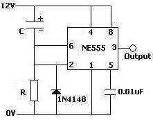
Connecting everything up for the final system is also very simple. The 12V supply voltage passes through the float switch or liquid sensor and into our circuit. The output (from pin 3 of the NE555 IC) connects to one end of the relay coil * with the other end connected to the ground (labelled 0V).
* Note in the diagram below the diode running parallel to the relay coil to protect the NE555 from high voltage spikes when the coil is de-energised..
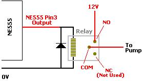
The relay can be fitted onto the circuit board with the NE555 chip, resistor, and capacitors making a simple plug-and-play integrated unit as shown below.
Buying a Pump Time Delay Circuit
If you would like to purchase a complete soldered circuit pre-set with a 10 second (or any other) time delay, a fitted relay and an LED water-detected indicator for £9.99, contact neil@reuk.co.uk. We sell a range of complete circuits in the REUK Shop, as well as liquid sensors and float switches.