A Zener Diode is an electronic component which can be used to make a very simple voltage regulator circuit. This circuit enables a fixed stable voltage to be taken from an unstable voltage source such as the battery bank of a renewable energy system which will fluctuate depending on the state of charge of the bank.
Zener Diode Voltage Regulator Circuit
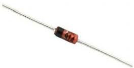
Pictured above is a very simple voltage regulator circuit requiring just one zener diode (available from the REUK Shop) and one resistor. As long as the input voltage is a few volts more than the desired output voltage, the voltage across the zener diode will be stable.
As the input voltage increases the current through the Zener diode increases but the voltage dropremains constant – a feature of zener diodes. Therefore since the current in the circuit has increased the voltage drop across the resistor increases by an amount equal to the difference between the input voltage and the zener voltage of the diode.
Matching the Zener Diode and Resistor to the Situation
Here is a hand-worked example which shows how to choose the correct zener diode and resistor for a known load: we have an unstable 12 Volt supply voltage and need a stable output of 8 Volts to power a 100mA device. 12 volts is sufficiently above 8 volts to ensure that any ripples in the supply will not take us below our target voltage.
1. Choose a Zener Diode
Since we need 8 Volts we can choose between a 7.5V or an 8.2V zener diode. 8.2V is close enough to our target voltage so we choose a zener diode with an 8.2 Volt zener voltage.
2. Calculate the Maximum Current in the Circuit
Our load device needs 100mA of current, plus we also need at least 5mA for the zener diode, therefore lets set Imax as 110mA to be safe. If you add 10-20% to the load current, this will give you a safe value for the maximum current in the circuit as long as the input voltage is unlikely to jump much higher.
3. Select the Power Rating of the Zener Diode
Zener diodes are available in a range of difference power ratings. If a large current flows through a small zener diode it will be destroyed, therefore we calculate the power to be lost in the diode and select a diode rated above that value. Here the zener power rating is equal to the zener voltage multiplied by the maximum current (Imax) calculated above which equals 8.2 * 0.110 = 0.9 Watts. Therefore a 1.3 Watt power rated zener diode should be perfect.
We multiply the full maximum current by the zener voltage since when no current is flowing through the load – e.g. when the device is switched off – all of the current will flow through the zener diode.
4. Select the Resisitor
The voltage dropped across the resistor is equal to the difference between the source voltage and the zener voltage = 12-8 = 4 Volts, and therefore the resistance according to Ohm’s Law is the voltage drop divided by Imax = 4/0.110 = 36 Ohms so choose a 39 Ohm resisitor.
If the source voltage is likely to be much over the 12 Volts stated then the voltage dropped across the resisitor will be larger and so a resistor with a larger resistance may be required.
5. Select the Power Rating of the Resisitor
The power dissipated in the resistor is equal to the voltage drop across the resistor multiplied by Imax. Therefore in this example power = 4 * 0.110 = 0.440 Watts. Using a 0.5 Watt resistor would be cutting it a bit fine – particularly if the source voltage is going to fluctuate higher regularly, therefore a 1 or 2 Watt rated resisitor should be used here despite it costing a few pennies extra.
Renewable Energy System Battery Bank Situation
If the above situation is referring to a renewable energy system battery bank, the 12V source voltage could vary from as little as 10.6 Volts to as much as 15.5 Volts. Therefore we need to check that everything still works correctly at the higher and lower voltage.
If the source voltage rose to 15.5 Volts then we would have 15.5-8.2 = 7.3 Volts dropped across the 39 Ohm resistor: a current of 187mA. If the source voltage fell to 10.6 Volts then we would have just 10.6-8.2 = 2.4 Volts dropped across the 39 Ohm resisitor: a current of 61mA. Therefore in both cases we easily have enough current passing through the zener diode to ensure a stable output voltage will be maintained.
At maximum voltage we would have 1.37 Watts of power dissipated by the resistor – therefore it is good we chose a 2 Watt rated model. We would also have a potential maximum of 1.5 Watts dissipated by the zener diode – therefore we should also change this to a 2 Watt rated model to be on the safe side.
Alternatives to Zener Diode Voltage Regulators
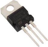
If you require a certain fixed output voltage – e.g. 5V, 12V, 15V from a given input voltage, there are a wide selection of linear regulator chips available. For example the L7805 for +5V (pictured above) and L7812 for +12V are the most popular. These just need capacitors on the input and output side to smooth the voltages, and are very reliable.
Where an adjustable output voltage is required, the LM317 is the common choice – see our articleLM317 Adjustable Power Supply for details of both low current and high current power supply designs with the LM317.
Where the input voltage is very close to the output voltage, an L7812 or LM317 for example cannot be used as the output from these ICs is always at least a couple of volts less than the input voltage. In these situations an LM2940 low dropout regulator or an adjustable LM2941 is a better option as the output voltage can less than 0.5V lower than the input voltage. These are particularly useful where voltage sensitive 12V lighting and devices are to be powered by a ’12V’ battery – particularly if that battery is to be charged via a solar panel or alternator etc.