Relays are a vital component of many renewable energy applications, particularly where the output from a low voltage low current electronic controller is used to switch a high current device such as a pump, motor, or heater.
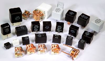
For applications where a load current of under 10 Amps is to be switched there are many relays available which can be PCB mounted (e.g this 10A relay available in the REUK Shop) and are not very expensive. When higher levels of current are to be switched, then PCB mounted relays are no longer suitable and here is where automotive relays come into their own.
Automotive Relays
As the name indicates, automotive relays are designed for use with cars. Cars operate on a 12 Volt system, and so (as Ohm’s Law tells us that current = power/voltage) high power devices such as amplifiers and air-conditioning units draw very high currents. A 300W amplifier for the stereo for example will draw a current of 300/12 = 25 Amps, and so a high current switching relay is essential.
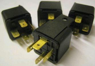
As there are so many cars manufactured with so many relays, automotive relays are typically not too expensive while also being very well made, robust, and relatively indestructable. This makes them the obvious choice for anyone who needs to switch a high current device.
Types of Automotive Relay
The commonest type of automotive relay is rated at 40A, with 30A and 20A coming close behind. Automotive relays typically have either 4 pins or 5 pins. In both cases two of the pins are for the coil across which 12V is put to act on the internal switch in the relay. This is called energising the coil.
The coil is literally a coil of thin enamelled magnet wire wrapped around an iron core. When voltage is put across the ends of the coil (energising the relay) the iron core becomes magnetic and attracts a contact arm which closes (or opens depending on the type of relay) a switch.
Where a PCB mounted 12V relay will typically need a current of 30-60mA to energise, large automotive relays require from 100mA – 200mA, with higher current rated relays typically requiring a higher energising current since they contain a bigger switch to be physically moved by the coil.
Almost all automotive relays on sale today are ISO standardised. Therefore, unlike with PCB mounted relays, the ISO mini relay connection diagrams pictured below should be valid for pretty much any 1″ cube sized automotive relay you find. (An alternative not often used are ISO micro relays which are half the thickness of ISO mini relays.)
 |
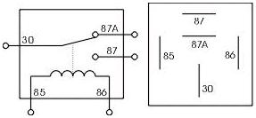 |
In 5-pin relays (pictured above), the three (non coil) pins are labelled COMMON, NO (normally open), and NC (normally closed). When the coil is energised COMMON is connected to NO, and when the coil is not energised COMMON is connected to NC.
 |
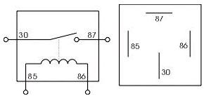 |
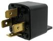
In 4-pin relays (pictured above), the non-coil pins are connected either side of the internal switch. This switch is open when the coil is not energised, and closed when it is energised. (This is equivalent to the available contacts being COMMON and NO (normally open). (Normally closed relays are also available which work in the opposite way – i.e. internal switch is closed unless the relay is energised.)
Using Automotive Relays
With PCB mounted relays it is very easy to either solder leads onto the pins or solder the relay onto a circuit board. With automotive relays things are a little more complicated since the pins need to be so much larger and the cable must be much thicker in order to carry large currents.
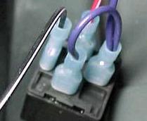
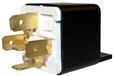
Therefore the pins of automotive relays are typically shaped to match standard female 6.35mm spade connectors. These can be crimped or soldered onto the ends of cables, and then simply pushed onto the relay pins making a very secure connection which can be disconnected if required to replace a relay or move wiring etc.
There is usually a small diameter hole in the middle of each spade which is useful if you want to connect thin gauge cable to the relay coil spades since it can be difficult to crimp spade connectors to thin cable. Strip the insulation from the end of the cable and feed the wire through the hole and solder it to the spade on the other side for a secure connection.
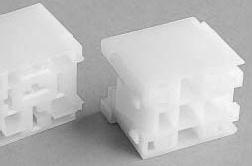
Automotive relay holders (pictured above) are also available. These can be clipped together to enable multiple relays to be fitted securely and tidily in an enclosure.
Voltage Spikes and Suppression
When a relay de-energises, the magnetic field generated by the coil collapses which induces a reverse polarity voltage spike of up to a few hundred Volts. As automotive relays generate a large magnetic field, this can cause serious and expensive problems.
In order to prevent a voltage spike from damaging any sensitive electronics which you may have connected to the relay coil – for example if you switched the relay via a transistor from an Arduino – you must fit a [de-spiking / clamping] diode parallel to the coil. This allows the back EMF spike to flow around from one end of the coil to the other instead of travelling through your circuitry. Voltage suppression relays are available, but are not very common and are more expensive. These relays contain resistors, capacitors, and/or diodes to suppress voltage spikes ensuring they never even get out of the relay.
Buy Automotive Relays
There are always a great selection of automotive relays of all the types mentioned above as well as automotive relay accessories listed for sale on eBay at affordable prices. Click here to search now for Automotive Relay to view the latest listings.