We are currently working on a project which has been updated to require the use of a 5 position rotary selector switch (knob). Each position of this switch corresponds to one mode of operation of the full device, and so we need our microcontroller to know which of the five possible positions the switch is in at any given time.
Unfortunately, due to the amount of inputs and outputs already connected to the microcontroller (PICAXE-18M2) used in this project, there is only one spare pin left – but it is an ADC pin (analog-to-digital converter) so all is not lost.
We decided to use something along the lines of a resistor ladder (Wikipedia link), but simplified to reduce the component count as the circuit board is already pretty full.
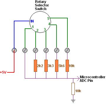
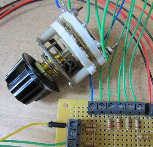
The image above shows the selector switch with +5V going into it up the blue wire, and then the wires corresponding to each position of the switch coming down the five green wires. When in position 3 for example, +5V is present on the third green wire, and the rest of the green wires are connected to nothing.
If we had lots of spare IO on the microcontroller we could just connect each of the five switch outputs directly to five individual microcontroller pins (not forgetting to add pull down resistors). What we instead had to do is put together the following very simple circuit.
 When the switch is in position one, +5V goes straight into the ADC pin on the microcontroller. When the switch is in position two, a voltage divider (Wikipedia) is formed with Vs = +5V, a 2k2 (2,200 Ohm) resistor as R1 and a 10k resistor as R2. Therefore the ADC pin will see Vo which is Vs * (R2/(R1+R2)) = 4.10 Volts. Switch position three sends 5V through a 3k3 10k voltage divider outputting 3.76V, position four through a 5k6 10k voltage divider outputting 3.21V, and position five through a 10k 10k voltage divider outputting 2.50V.
Using the 10-bit ADC pin on the 5.00V powered microcontroller, a numerical value from 0-1023 is assigned proportional to the voltage (0-5V) arriving on the pin. So, position one (analog 5V) is given the digital value 1023, position two (4.10V) is 839, position three (3.76V) is 769, position four (3.21V) is 657, and position five (2.5V) is 512.
These calculated ADC values will not be exact as the resistance of the resistors will change a little with temperature, the 5V regulator feeding the microcontroller may fluctuate a little etc – therefore, we actually use ranges instead of exact values to work out within software which switch position is selected – e.g. position three is 769, but as position two is 839 and position four is 657, we can say that the switch is in position three if the ADC value from the arriving voltage is in the range 714 to 803.
This is all relatively simple to set up in the software – we just added a short PIcaxe subroutine called whichMode which does the readadc10 command on the relevant pin and sets a variable modeValue to the mode value (1,2,3,4 or 5) to which the ADC value corresponds.
