These are the instructions for putting together the 3 Phase Bridge Rectifier Kit available from the REUK Shop. Please read them through fully before starting to assemble your bridge rectifier kit.
Identifying the Kit Components
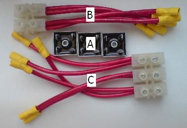
The kit is made up of three main components. Three MB356 35 Amp Bridge Rectifiers (A), one positive/negative connector (B), and one three phase connector (C).
The Bridge Rectifiers
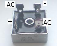
Each bridge rectifier has four legs – one positive leg (labelled on the side of the metal cladding with +, one negative leg (diagonally opposite the postive), and two AC legs (one is labelled AC on the cladding with the other diagonally opposite).
The Connectors
The positive/negative connector has three wires coming out of each of two terminal blocks. The three negative wires are marked with a ring of black insulating tape. The other three wires are the positives.
The three phase connector has two wires coming out of each of three terminal blocks.
The yellow insulated crimp connectors fitted to the end of each wire are all labelled with either I, II, or III indicating the bridge rectifier to which they should be connected.
Building the Kit
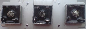
The three bridge rectifiers should ideally be screwed or bolted to a suitable heat sink. They should be positioned at least one inch apart so that any heat generated within them is dissipated. The bridge rectifier on the left will be called I, the central bridge rectifier II, and the bridge rectifier on the right III.
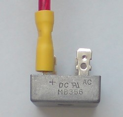
Plug the three positive connectors (those at the end of the positive wires) to the + legs of the three bridge rectifier – wire I to bridge rectifier I and so on. Do the same with the negative wires connecting them to the leg diagonally opposite the + leg of each bridge rectifier.
There are two wires for each phase of the AC electricity input – two for bridge rectifier I, two for bridge rectifier II, and two for bridge rectifier III. Plug the two connectors labelled I from the three phase connector onto the AC legs of bridge rectifier I, and do the same with the connectors labelled II and III with bridge rectifiers II and III respectively.
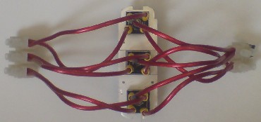
Your three phase bridge rectifier is now complete!
Connecting the Bridge Rectifier
It is very simple to connect your new bridge rectifier into your renewable energy system.
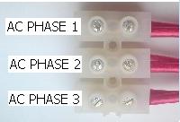
The three live wires from your wind turbine or other AC electricity generator should be inserted into the three holes on the three phase connector and locked in place by tightening the locking screw. Which live wire goes into which hole is not important.
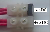
The negative DC output wire should be inserted into the negative terminal of the positive/negative connector (labelled with black insulating tape), and the positive DC output in the other hole.
Useful Advice
The supplied bridge rectifiers are very robust, however you need to be careful. The connected wires give a lot of leverage and so it is possible to accidently bend a bridge rectifier leg. This will not cause the bridge rectifier to fail however repeated bending of a leg may eventually lead to metal fatigue and component failure.
When plugging and (particularly when) unplugging the connectors from the legs of a bridge rectifier always push/pull the yellow crimp connector rather than tugging on the wire. Repeated strong pulling of the wire could cause the crimp connection to come loose and/or bend a bridge rectifier leg.
When selecting a heat sink, SIZE MATTERS. The bigger the better. Ideally squirt some heat sink compound between the bridge rectifiers and the heat sink to help the generated heat to dissipate. The heat sink pictured in these instructions is small for three bridge rectifiers. However, with each bridge rectifier given a heat sink such as this (reclaimed from an old Pentium II PC and easily available for 10p or 20p at car boot sales etc), then it would cope well with higher currents.