In our article PIR Sensor Circuits we looked at how a PIR Sensor can be used in an automatic security or lighting system. We recommend you read that article before reading on.
Connecting Two or More PIR Sensors
There are many situations in which it is necessary to use more than one PIR sensor within a system – in particular, where security lights along the side of a house are controlled by one PIR sensor at the rear and another PIR sensor at the front. In this article we will demonstrate how two or more PIR sensors can be connected together and their combined output used.
n.b. This article is written for 12 Volt DC powered PIR sensors such as the Honeywell IS-215T (for sale in the REUK Shop). Different PIR sensors – particularly those powered by mains electricity may operate differently.
Understanding the Output from a PIR Sensor
When a PIR sensor detects motion, it outputs 0V; when no motion is detected it outputs 12V. Inside the PIR sensor are two screw-in terminals labelled C and NC. To the C, the installer connects +12 VDC. When motion is not being detected, C and NC are electrically connected, and so a +12 VDC signal comes out of the NC (output) terminal. When motion is detected, this electrical connection betweenNC and C is broken, and the output from NC goes to 0 VDC.
The property described above makes it very easy to connected multiple PIR sensors to one another so that if one or more detects motion, a 0V output be generated. In order to achieve this the PIR sensors must be connected in series.
Connecting Multiple PIR Sensors In Series
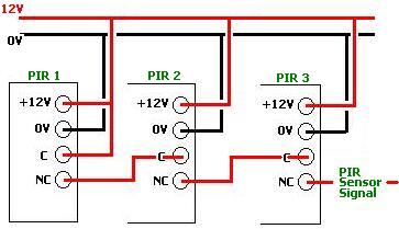
Above is a schematic diagram showing how multiple PIR sensors can be connected in series with each other so that if one sensor or more detects motion, the final output signal will be 0V. When none of the PIR sensors are detecting motion the output signal will be +12V as it should be. This way of joining PIR sensors will work equally well for 2 or 20 sensors as long as just one output is required, and the detection of motion by any of the PIR sensors is significant.
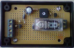
Pictured above is a circuit which takes an input from one (or more series-connected) PIR sensors. When motion is detected, the relay on the circuit board will close for from 5-80 seconds (user programmable) turning on a connected device – e.g. security light or warning siren.
Click here to find out more and/or to purchase the REUK PIR Relay Timer now.