In our article Automatic Hen House Door Closer/Opener we showed how to overcome the difficulty of getting a motor to turn one way to open a door and turn the opposite way to close a door. We offered programmable timer based and light detector based products for sale which used a microcontroller to decide when to open/close the door and also to control the motor’s direction of rotation and duration of rotation. At that time we were also recommending that people use windscreen wiper motors to raise and lower the door as they were relatively cheap and easy to find.
In the four years since first publishing that article we have put together a few hundred of these door control systems learning a lot on the way, so it is now time to share what we have learned.
The Motor
Windscreen wiper motors are physically quite large, and take a lot of power. Also, if the door jams on its way up or down, the current pulled from the battery by the restricted motor can be very high – high enough to damage 10A relays, and overheat cables not sized for such high currents etc.
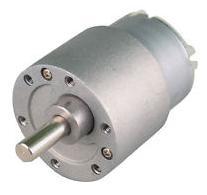
After a lot of experimentation during which we tested a huge range of motors, we found 30 RPM high torque motors (such as the one pictured above) are the best for this application. These motors are relatively small, are very strong, turn slowly (30 times per minute thanks to the built in gearbox) giving good control, and use very little power. At 12V, one of these motors draws around 40mA when not loaded or with minimal load, going up to less than 1A when the motor is physically prevented from turning at all. They are also very cheap at around £5-8 delivered. Click here for more information and/or to buy one of these motors now: 30 rpm high torque 12V geared motors.
Limit Switches
Our standard controller had to be programmed by the user to the number of seconds the motor has to run to open the door, and the number of seconds the motor has to run to close the door. A digital programmable timer or light detector (dawn/dusk detection) is then used to set the times of day when the door is to operate. This works well in general, but sometimes the door moves more slowly than at other times (e.g. when wet, snowy, or snagged on something) and in those cases there is a risk of the door not fully closing/opening.
We have found that the best way around this is to use limit switches so that the motor runs until the door is fully open and then stops, or runs until the door is fully closed and stops.
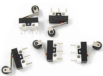
We have found that the type of roller microswitches pictured above give reliable operation. You mount these at the side of the door in the position that the bottom of the door will be when a) the door is closed, and b) the door is open. A small piece of wood or similar stuck to the side of the door at the bottom will then keep the lower limit switch closed when the door is closed, and the upper limit switch closed when the door is open.
Click here for more information and/or to buy this type of roller switch.
The Controller
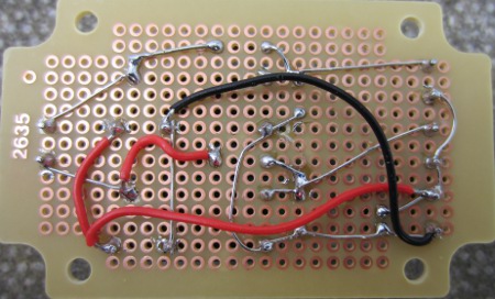
With a good motor, and limit switches in place, that just leaves the new controller. We have come up with a new simple design which does not need a microcontroller, just a 12V programmable digital timer, two SPDT relays, and four 1N4001 diodes.
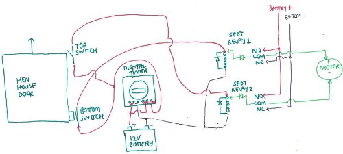
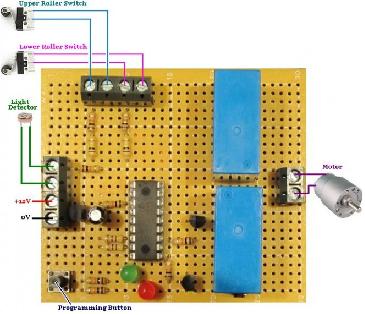
Common SPDT relays are used (Introduction to Relays) in this controller. The right hand side of the diagram above achieves the polarity switch to enable the motor to spin in both directions. When relay1 is closed the motor will turn one way, when relay2 is closed the motor will turn the other way, and when relay1 and relay2 are both closed or both open the motor will not turn. (See here for details of how that works.)
It is morning and the timer is programmed to come on for one minute. The door is closed so the bottom switch is also closed. Therefore the positive from the battery is connected via the timer and the bottom limit switch to the coil of relay1 which immediately energises it. This connects COM to NO and so since COM is also connected to the coil of the relay and NO is connected to the battery positive, the relay latches – i.e. stays energised even when the door opens and the bottom switch opens. (see here for details of how that works.)
When the bottom of the door reaches the top limit switch the positive from the battery is connected via the timer and the top limit switch to the coil of relay2 which energises it, and it latches in the same way that relay1 latched. Now both relays are energised, the motor stops turning.
After a short while the timer turns off.
Then in the late afternoon, the timer comes on again for one minute. This time the top limit switch is closed and the bottom limit switch is open, so relay2 latches and the motor starts turning (in the reverse direction to that of the morning) to close the door. When the door gets down to the bottom limit switch relay1 latches, so as both relays are energised the motor stops turning. Shortly afterwards the timer turns off.
There is a diode across the coil of each relay to protect against back EMF. There is also a diode connected between COM and the coil for each relay (note the polarity of this diode). When one of the switches closes, battery positive is connected to the side of the relay coil which is also connected to the relay’s COM. At this time NC and COM are still connected (since the relay is not yet energised) and battery negative is connected to NC – therefore without the diode there blocking, there would be a short circuit. (DPDT relays could be used to give two sets of NO-COM-NC terminals to use and then the diodes would not be necessary, but DPDT relays are more expensive and there would be more wiring to do).
More Information
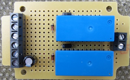
If you have any questions about this controller design or if you would like us to make you a controller board of the type pictured above, please email neil@reuk.co.uk. We can also supply 12V digital programmable timers suitable for this application and/or the component parts to make your own controller.
If you would prefer to have a light detector based controller which can automatically detect dawn and dusk and run the motor then we can make these for you either with or without limit switches depending on your preference. Click here for an example of such a controller (pictured above) which we make:Dawn Dusk Automatic Hen House Door Controller.