 To find out more about using solar power with wireless CCTV take a look at our article: Solar Powered Wireless CCTV.
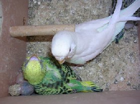
Nestbox CCTV
Unless the CCTV receiver is to be more than 100 feet away from the nestbox choose a 50mA wireless camera.
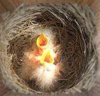
If you would like to be able to view nocturnal activity then an infrared wireless camera is the best choice since the infrared light will not be visible to the nestbox inhabitants.
If you would like to view daytime activity, then one or more ultrabright white LEDs can be used to illuminate the interior of the otherwise dull nestbox.
If the camera is to be left on 24 hours per day the amount of battery capacity and the solar panel required will be quite large (and expensive), therefore in this article we will introduce plans which will enable the camera to be operated at least four hours per day with just 8 AA rechargeable batteries for storage and a 12 Volt solar panel of around 2-4 Watts capacity. When not in use the camera and interior lighting can be switched off leaving the solar panel to keep the batteries charged up.
It is possible to put together a system which will automatically turn on the camera either at night or during the daytime, but this is more complicated and requires the solar panel to be situated in a position with no shade.
Putting Together the Circuit
Below is the circuit used to power the CCTV camera, provide lighting inside the nestbox, and charge batteries from a PV solar panel.
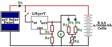
D1 is a Schottky Diode used to prevent battery charge escaping through the solar panel at night. Something like a 1N5817 (1 Amp 20 Volt diode) will do the job and it has a very low voltage drop of under 0.45 Volts. D2 and D3 are ultrabright LEDs used to illuminate the inside of the nestbox. R3 and R4 are resistors chosen (400+ Ohms) to ensure that no more than 30mA of current gets to the sensitive LEDs, with R5 (a 10k variable resistor) used to increase the resistance and therefore dim the LEDs if they are too bright.
The LM317T is a voltage regulator * used to bring the voltage of the solar panel and batteries down to just over 8 volts using resistors R1 (270 Ohm) and R2 (1500 Ohm) to set this value. K is the wireless CCTV camera.
A switch (not labelled) is used to manually turn the camera on and off as required.
* Click here to find out more about using the LM317 to regulate voltage.
NEW The REUK Shop now has complete LM317T-based 8.5V voltage regulators for sale which are perfect for use within solar powered wireless CCTV systems.
If the solar panel chosen is not too large there is no need to worry about overcharging the batteries, and so there is no need to use a solar charge controller. Using 8 AA batteries in series will provide the 8+ Volts required by the camera, and the LM317 will prevent excessive voltage getting to the camera while the batteries are being charged by the solar panel.
Capabilities of this Nestbox CCTV System
If a 50mA wireless CCTV camera is used then the output power requirements of this circuit are around 100mA. The solar panel should be selected such that it puts a little more power into the batteries than the camera and LEDs are using. If a 2 Watt 12 Volt solar panel is used then it will be putting around 160mA into the batteries (and/or into the camera) during the 4-5 hours of strong sunshine daily. As long as the camera is on for less than 4 hours per day then this panel should be sufficient.
Since the capacity of the rechargeable batteries in this example is 2,700mAh, the maximum charging current from the solar panel should be less than 270mA (C/10), therefore a panel of no more than around 3.5 Watts should be used unless more battery storage is used (for example a small sealed lead acid battery or a second string of 8 AA batteries in parallel with the first string).
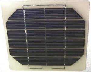
During testing we used two of the 6 Volt 250 mA Solar Panels (pictured above) in series to generate the necessary 250 mA at 12 Volts to keep the batteries charged and the camera in operation for five or six hours per day.
Putting Everything Together
It is essential to keep the batteries, circuit board, and switch waterproof. Therefore an airtight tupperware container was used to hold the circuit board and batteries. Wires come into and out of the box via small holes drilled in its side and sealed with silicon. The two solar panel leads go in, and the leads for the two LEDs, the camera, and the on/off switch come out.
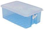
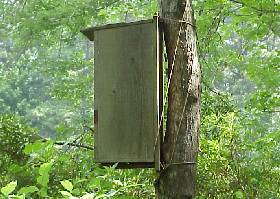
The lid of the container used to protect the vulnerable circuitry and batteries can be screwed to the underside of the base of the nesting box. The switch can be kept watertight inside a small balloon.
The LEDs will be protected from the elements inside the nestbox and should be fitted into the two corners above the nestbox entry hole with the camera fitted above the entry hole toward the top of the nest box and pointed down. If the camera or LEDs are fitted elsewhere the bright light coming in through the entry hole (relative to the dark interior of the nestbox) causes shadows and silhouettes which make viewing difficult.
The variable resistor should be used to reduce the brightness of the LEDs as much as possible while still illuminating the nestbox sufficiently for the camera.