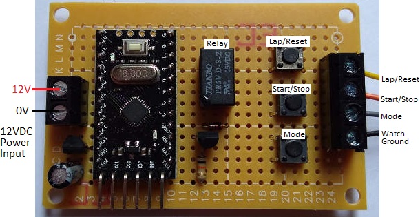
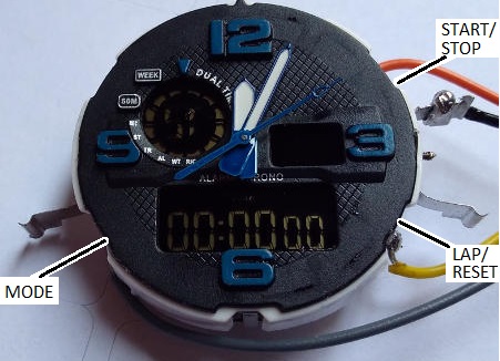
Pictured below are the inner workings of a cheap digital watch which has been modified to enable remote operation of the buttons so it can be used for automatic stopwatch timing.
This particular watch had a broken backlight and broken strap, but it had always kept very good time. Therefore it was a perfect candidate to be re-purposed.
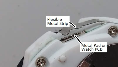
The watch had rubber button tops integrated into the watch case. When the workings are removed from the case, the buttons themselves are exposed. They comprise a thin strip of metal separated from a metal pad on the watch PCB. When the rubber button top is pressed down, the metal strip makes contact with the metal pad making an electrical connection.
All of the metal strips are connected to the watch battery ground, so the watch detects button presses by waiting for 0V to appear on one of the metal pads (which are electrically connected to the microcontroller inside the watch).
We soldered wires to the three metal pads of the buttons we wanted to control, and a ground wire to one of the commonly connected metal strips. Shorting the end of this ground wire to the end of any of the other wires causes the relevant button operation to take place.
 We next made the above pictured board. We put three tactile switches on the board and wired them up so that when pressed, they would short a mode button input to ground. These tact switches make it much easier to interact with the wired-up watch manually.
Then we added a small 5V coil relay and connected its NO and COM pins to the Start/Stop button connection and to ground for the watch. When the relay is energised (closed) it will simulate the Start/Stop button of the watch being held down.
The final component is an Arduino Pro Mini in a socket. This board will be used to calibrate the internal clocks of Arduino Pro Mini clones as their crystals are not accurate enough for some of the projects we build.
(Note that we are powering this board with 12VDC for convenience as that is the voltage we use for all of our testing rigs with a bench power supply, but for a one off it would have been 5VDC powered – 4 AA cells for example.)
Controlling the Stopwatch via Arduino and Calibrating the Arduino’s Internal Clock
 digitalWrite(relay, HIGH);
 delay(50);
 digitalWrite(relay, LOW);
The Arduino code above is used to briefly energise the relay which starts and stops the stopwatch. We used a 50 millisecond delay so that the relay has time to energise (physically close its internal contacts) and button presses of under 20 milliseconds were ignored by this watch. When someone presses a button, they typically keep it held down for from 30-70 milliseconds, so we replicated that.
To roughly measure how long is 10 seconds for the Arduino, we used the following code:
digitalWrite(relay, HIGH);
delay(50);
digitalWrite(relay, LOW);

delay(10000);

digitalWrite(relay, HIGH);
delay(50);
digitalWrite(relay, LOW);
It starts the stopwatch, waits 10,000 milliseconds, and then stops the stopwatch. If the Arduino is accurate, the stopwatch will stop with 10.00 seconds displayed. In a few quick runs we got 10.03, 10.07, 10.06, 10.06, 10.03, 10.03, and 10.06 seconds. This seems to show that this particular Arduino Pro Mini was running a little slow (it could also be that it takes longer for the relay to energise than de-energise which could be significant when only timing 10 seconds).
The delay() function is not accurate in general since we do not know how long the loop execution time is. Instead for accurate time testing we use millis().
Replacing delay(10000); with the following:
unsigned long startTime = millis();
do{
  delay(1);
} while (startTime + 10000> millis());
we got 10.00, 10.00, 10.00, 10.00, 10.00, 10.00, and 10.00 seconds on the stopclock in initial testing.
For calibration we test for a minimum of 8 hours, but sometimes 12 or 24 hours. The longer the test, the greater the accuracy of the results and therefore the better we can calibrate the Arduino’s internal clock.
There are 28800000 milliseconds in 8 hours for example. So we’d modify the code above to have while(startTime + 28800000 > millis()); . After 8 hours, the stopwatch will show a time. We found that that this Arduino Pro Mini was running 4 seconds slow….so after 8 hours the clock showed 8h 00m 04s.
There are 28,000 seconds in 8 hours, so the error in the Arduino clock is
1 – 28,000/28004 = 0.0001428 = 0.01428%.
We can save this percentage error in memory on this Arduino Pro Mini and take it into account when using it in timing applications. If we want to use this Pro Mini to time 5 hours accurately, we’d run the timer for 5 hours minus 0.01428% of 5 hours.

