Project of the Day – Swimming Pool Solar Water Heating Controller with Max Temperature

Today we have been working on a new solar water heating pump controller for use with a swimming pool with a user-settable maximum water temperature. This can be used to keep hot tubs at a safe temperature, or keep a swimming pool from getting unpleasantly hot.

This new device is based around our latest 2013 Solar Water Heating Pump Controller with the new features added on.

Swimming pool solar water heating controller with max temperature control
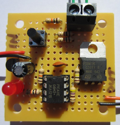
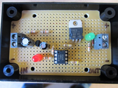
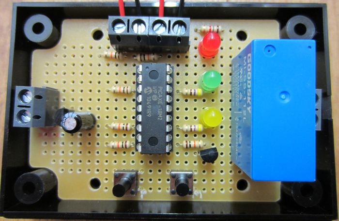
In terms of hardware we have moved from a PICAXE-08M2 to a PICAXE-18M2 for its additional input/output pins, and then just added the yellow LED and second push button.

The operation of the controller is unchanged from the 2013 controller with the addition of the following functionality:

User can set maximum temperature the pool should reach to 1 degree accuracy from 25 degrees Celcius up.

If pool reaches the maximum temperature, the pump will turn off and not turn on again until the pool temperature has fallen by at least 2 degrees Celcius (hysteresis).

User can disable the maximum temperature feature or enable it with the push of a button.

If you need a controller of this type for your solar heated pool or hot-tub, do not hesitate to contact us via the REUK.co.uk website.

Multiple Buttons/Switches on one ADC Input

Small microcontrollers are cheap and easy to use, but one problem they have is a shortage of IO pins (input output). If you have a lot of inputs (e.g. sensors, switches, buttons etc), and outputs then a larger (more expensive) microcontroller is often required.

There is a good way around this problem when there are a lot of switches or buttons to detect; an example is shown below with three push to make buttons:

multiple switches connected to one microcontroller pin ADC

Instead of connecting the buttons to separate digital input pins on the microcontroller, each button can instead be connected up to different value resistor as shown above, and the combined output connected to an ADC (analogue digital converter) pin on the microcontroller.

When no buttons are being pressed, the ADC pin sees 0 volts thanks to the pull down resistor. If the top button is pressed, a voltage divider is formed with R1=47K and R2=10K, so the ADC pin sees 0.877V. If the middle button is pressed, a voltage divider is formed with R1=10K and R2=10K, so the ADC pin sees 2.500V. And if the bottom button is pressed, a voltage divider is formed with R1=1K and R2=10K, so the ADC pin sees 4.540V. The ADC pin monitors the voltage and by comparing the detected voltage with the known values for each button, the microcontroller will know which button has been pressed.

This is an excellent technique to use for up to around 10 buttons. Just remember that if more than one button is likely to be pressed at the same time things get a lot more complicated – particularly when there are a lot of buttons.

Standalone Arduino on a Breadboard

arduino duemilanove microcontroller board

We have used Arduino boards in many of our projects. For those that do not know, Arduino is described as an open-source electronics prototyping platform and is basically a microcontroller on a preassembled board with a good selection of IO (inputs and outputs) and availability of shields (add-on circuit boards to help with internet connectivity, motor control, and much more) which can be connected. The boards have a USB socket through which code is downloaded to the board and also to enable control of devices via a PC.

Although Arduino boards are relatively cheap, starting from around £10 each (click here for best priced Arduino boards), things start to get expensive when you do multiple custom embedded projects – particularly when you are not using the majority of the features provided on the board.

Fortunately it is possible to buy the microcontrollers which are found on the Arduino boards separately, add just a few components (a clock crystal, and a couple of capacitors), and build the rest of your project around that.

standalone arduino kit - microcontroller, crystal, and capacitors

The common Arduino duemilanove board for example has an ATMEL ATmega 328 microcontroller which are easy to purchase BUT a blank microcontroller is not enough. It must have the correct Bootloader (software) on it before you can use it with the Arduino programming environment and USB connection. This is a job you can do yourself (with an ISP programmer), but for most people it will be much easier and cheaper just to purchase a kit such as the one pictured above which we use and available here for around £3 (Arduino Bootloader Kit). These have the bootloader pre-installed on the microcontroller and include a PCB socket, and the capacitors and the external 16MHz clock crystal.

Standalone Arduino circuit

Using these kits means you only need one Arduino board which you use to download your code sketches to the microcontroller. You then unplug the microcontroller from the Arduino board and plug it in on your own project board.

Below is the ATmega168 / ATmega328 Arduino pin mapping diagram so you know which pins on the microcontroller correspond to the inputs and outputs labelled on an Arduino board.

arduino atmega328 and atmega168 pin mapping

Project of the Day – Use Surplus PV with Air Source Heat Pump

Since the introduction of feed in tariffs in the UK we have been selling our REUK Solar PV Immersion Controller (pictured below) the concept of which is described in our article Water Heating with Surplus Solar PV.

REUK solar PV immersion controller

This device uses a light detector to estimate the level of solar electricity generation, and if it exceeds a user set threshold it switches on an immersion heating element so that electricity generated in excess of what is needed can be used to heat water rather than being exported (sold) to the Grid for just a few pence per unit.

An immersion heating element is a very simple resistive heater which can be turned on and off repeatedly during the day (with fluctuating levels of solar generation) without coming to any harm. If instead our standard controller is to be used to switch an air source heat pump (ASHP) or similar complex device then there could be problems.

One of our customers wanted to use our controller to power his air source heat pump with surplus PV solar generation, but in discussions with the manufacturer was told that the ASHP should be run for at least 30 minutes each time it is turned on. We therefore modified our controller software so that after the ASHP turns on (following a period of consistent good solar generation) it will stay on for 25 minutes, and then only turn off after a 5 minute period during which 90% of the light level readings show bad solar generation.

The result of these changes is that there will be times when the electricity demanded by the ASHP exceeds solar generation and so electricity will have to be imported (bought) from the Grid to meet the shortfall. But, as air source heat pumps cost thousands of pounds, it is much more important to protect the equipment from damage than to worry about the few extra pounds incurred in importing mains electricity.

Project of the Day – RC Helicopter Lighting Controller

Today we made a controller to turn on the navigation lights on a radio controlled helicopter when it is dusk or dark outside.

RC Helicopter lighting controller

Being a small RC helicopter, the lighting controller had to be small in size and low weight. A basic transistor circuit with light detector would not have been up to the job since the navigation lights would flicker on and off when the light detector was at the ambient light/dark threshold. The controller therefore needed hysteresis to avoid this multi-switching. It also needed to be easy for the user to set the light/dark threshold at which the navigation lights turn off/on.

To keep everything small, we used a PICAXE-08M2 microcontroller for this project. To set the light/dark threshold we decided against using a potentiometer in case vibrations from the helicopter’s motor caused it to rotate away from the user set position. Instead we fitted a small tactile switch to the circuit board. If this is pressed and held (at dusk) while the controller is being connected to the battery pack, the light detector (mini LDR) measures the current ambient light level and stores this in memory (not lost when battery disconnected) as the light/dark threshold.

In standard operation, when the light level is measured to be brighter than the threshold continuously for two seconds, the output to the navigation lights is turned on. If subsequently the light level is measured to be duller than the threshold continuously for two seconds, the output to the navigation lights is turned off.

The dimensions of the controller are under 2 x 2 inches.

Project of the Day – Digital Photo Frame Low Voltage Disconnect

Today we put together a special order low voltage disconnect (LVD) to be used with a product display case containing a digital photo frame.

To make the case portable, instead of using the standard 5VDC power supply, 8 series connected high capacity C sized rechargeable cells have been fitted to give a 9.6V power supply which goes through a dc-dc voltage converter to get the required 5VDC to the photo frame.

Low voltage disconnect for digital photo frame

Unfortunately when the voltage of the 8xC battery pack falls to 8.7V (when the battery pack is almost empty of charge), the photo frame software crashes and gets stuck in a constant reboot cycle due to not having enough power to restart.

The low voltage disconnect we designed measures the voltage of the battery pack and if is more than 8.80V it outputs power to the voltage converter and photo frame. If the measured voltage falls below 8.80V, then the output is turned off and only turns back on again when the measured voltage is found to be greater than 9.20V.

The display case is fitted with a standard off the shelf battery charger which takes a 12VDC input. An external 12VDC power supply can be plugged into the case to recharge the battery pack while at the same time powering the photo frame via the low voltage disconnect circuit causing the disconnect to be cancelled (since the measured voltage is now 12V) and the photo frame to restart.

When the 12VDC is supplied, the 8xC cells are automatically disconnected from their series circuit and connected individually in parallel to the battery charger for charging. When charging is complete, the 12VDC power supply can be disconnected, the battery pack voltage will be >9.20V, and so the frame will continue unaffected.

We sell our own automatic user programmable low voltage disconnect in the REUK Shop. If you have any special requirements which this product does not meet, let us know and we should be able to put something together for you.

Project of the Day – 12V PIR Alarm System

Today we put together a 12V alarm system for a farm building located 100 metres from the farmer’s home. When motion is detected in the building by one or two standard , two relays close. The first causes a loud siren to sound, and the second turns on a bright strobe light visible from the farmer’s home.

PIR Alarm System with siren and strobeIf the controller is not reset by the farmer pressing an external panel mountable button then after 3 minutes the siren relay opens cutting the sound, but the strobe light is left turned on until the controller is manually reset to ensure that motion detection events are never missed.

If you need something along these lines then let us know. Click here for suitable low power consumption 12V strobe lights and/or low power high volume 12V sirens and sounders for your own projects.

12V Regulator for RC Planes, Helicopters, and Cars with Cameras

With the price of high quality ruggedised mini video cameras and transmitting equipment falling rapidly, many people are now attaching FPV (first person view) cameras to their radio controlled planes, helicopters, and cars with very impressive results.

View from RC plane camera

One common problem though is interference. When radio transmitting equipment is powered by the same power source as motors, servos etc, interference (noise) can add lines and other unwanted effects to the transmitted images.

The camera and transmitter need a very stable fixed voltage – e.g. 12.0 Volts – as anything else will damage the sensitive electronics. Therefore a voltage regulator is required. For their high efficiency and small dimensions a switching type regulator would appear to be the obvious choice, but this type of regulator generates yet more interference. Therefore a lower efficiency linear regulator must be used.

In the second half of this excellent article The Tricopter V2.6HV David Windestål from Sweden explains in detail how he built a very stable interference suppressing linear regulator around the LM2940 low dropout voltage regulator.

Very stable 12V linear regulator for RC

This is almost identical to our standard REUK 12V regulator but the components L1 (1mH coil) and C1 (low equivalent series resistance ESR also known as low impedance 22uF capacitor) have been added working together to make an LC filter (Wikipedia: electronic filter) to strip out any noise from the ESC (electronic speed controller) and everything else connected to the same battery pack.

Regulator for RC helicopter camera transmitter

With a 16.8V LiPo battery pack fitted in his DIY tricopter and a transmitter drawing 300mA, the regulator only has to get rid of 1.5W of heat, so only a small heatsink was required resulting in the finished regulator ended up small and light which transmits video which is “crystal clear [without] a hint of interference”.

Renewable Energy Use up to 13% of Gross Final Energy Use Across EU

Eurostat, the statistical office of the EU, has released its figures for renewable energy use across the EU27 – the 27 EU states – for the calendar year 2011. Of all energy use across the EU27, 13% came from renewable sources compared to just 7.9% in 2004 and 12.1% in 2010, well on its way to a target of 20% in 2020.

Looking at the countries individually, the top renewable energy users were Sweden (46.8%), Latvia (33.1%), Finland (31.8%) and Austria (30.9%), and the lowest were the tiny states of Malta (0.4%), Luxembourg (2.9%), followed by the United Kingdom (3.8%), Belgium (4.1%).

Between 2004 and 2011, the countries with the biggest gains in renewables usage were Sweden (38.3% to 46.8%), Denmark (14.9% to 23.1%), Austria (22.8% to 30.9%), and Germany (from 4.8% to 12.3%); while the UK went from 1.1% to 3.8% in the same time period. The EU target for the UK is 15% by 2020.

Click here for full details in the Eurostat 26th April 2013 press release: Share of Renewable Energy up to 13% of Energy Consumption in the EU27 in 2011.

Special Offer – Complete Evacuated Tube Solar Water Heating System

Complete evacuated tube solar water heating system

Pictured above is a complete DIY 30 tube evacuated tube solar water heating system for sale here in the UK at £1,662 plus £45 for delivery.

While that obviously sounds like a lot of money (as it is) you get a lot for your money all from one place thereby making savings in postage and the time otherwise taken to spec and source everything.

Evacuated tube solar water heating systems (click link for more information from REUK site) are the most efficient on the market today. A 30 tube system such as this fitted with a 200 litre tank will meet the majority of a typical family household’s hot water needs for 3 seasons of the year, and make a good dent in water heating bills the rest of the time – even when it is freezing outside.

The kit comprises the 30 evacuated tubes, 200 litre insulated twin coil cylinder, roof fittings, solar contoller and pumping station, expansion vessel, pipework, and all the other fittings necessary to put together a complete solar water heating system together with detailed instructions.

Click here for more information or to buy now: 30 tube solar water heating kit. There are many other options – e.g. smaller or larger systems available from the same seller. Click here to view the range: DIY evacuated tube solar water heating.