Replacing 30 Year Old Solar Hot Water Controller

Pictured below is the differential temperature controller fitted to a 1980’s solar hot water system. After many years of successful operation, this controller finally failed (pump stays on all the time) and needed to be replaced.

Old solar water heating pump controller
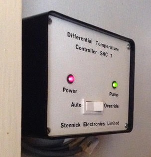
Something functionally identical was required, at least externally for the benefit of the user, so we were tasked to build a differential controller with relay to switch a mains powered pump, and to include a power on LED indicator, a pump on LED indicator, and a physical switch to select between standard automatic operation and ‘override’ which forces the pump to run.

Circuitry found in 1980's differential temperature pump controller

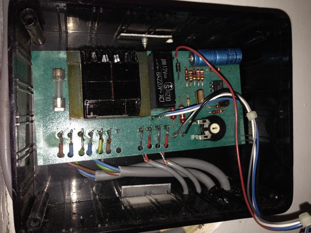
The internals of the old controller are pictured above. It shows a simple system with mains power going in and coming out again on its way to the pump switched by a relay, a transformer to get low voltage DC from the incoming mains AC, a potentiometer which is probably there for the installer to set the temperature differential required between solar panel and hot water tank for the pump to be turned on or to zero the measured difference when the sensors are at the same temperature, and the connections (two core) for two temperature sensors which are almost certainly going to be thermistor type sensors. There is also an IC visible which will most likely is a microcontroller, a 555 timer, or a comparator.

The sensor leads (and all other leads) were soldered in place upon installation, and the sensor cables were run through walls and are therefore inaccessible. Since the existing cables were 2-core, we had to build the new controller using sensors with two connections – LM335 – rather than the 3 connection digital sensors we use in most of our controllers – DS18B20 temperature sensors.

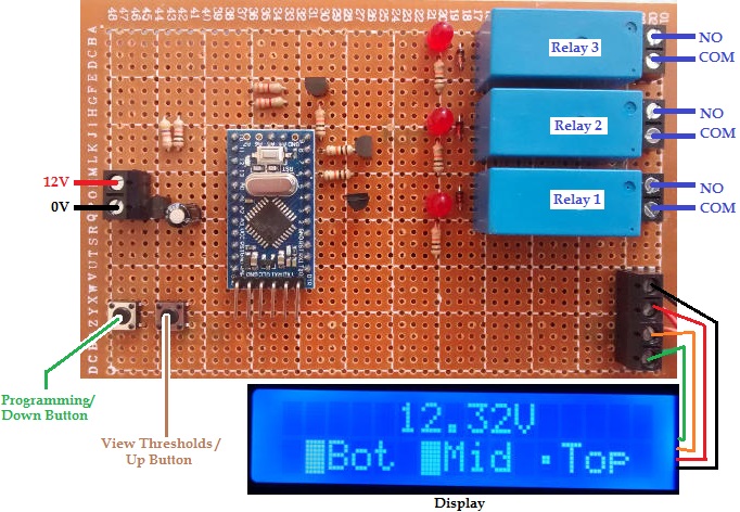
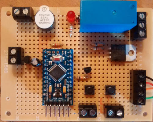
Our 2013 Solar Water Heating Pump Controller is the most similar unit we sell to this existing controller, so used that as the foundation of the controller we built.

modified 2013 solar water heating pump controller
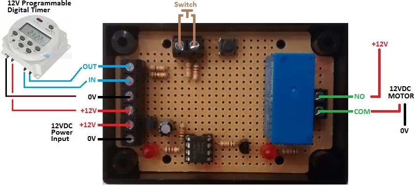
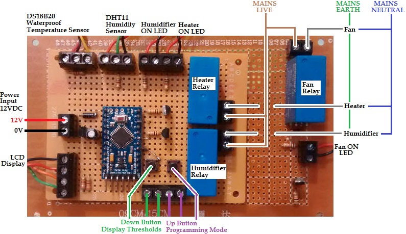
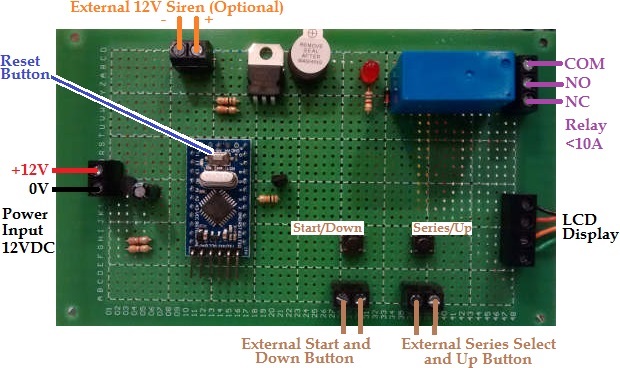
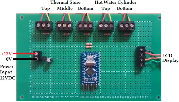
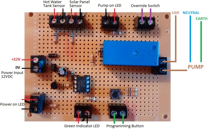
All LEDs, buttons, and switches have to be external to the controller board, so these have extended leads which connect via screw in terminals. We supplied a plug in 12VDC power supply rather than fitting a transformer directly to the circuit board, and we added an LED which turns on when the unit is powered, and the override switch which can be used to force the pump to run. We fitted the programming button (used to set the temperature differentials at which the pump turns on and turns off) to the circuit board, but connected terminals in parallel with it so that an external button can be panel mounted now or at a later date.

If you need a modified version of one of our differential temperature controllers, please email neil@reuk.co.uk with details of your requirements.

Low Voltage Disconnect for Glacial Movement Research GPS in Greenland

Pictured below is a special low voltage disconnect (LVD) device which we have been supplying for a few years for use by academic researchers in glaciology.

low voltage disconnect for glacial movement monitoring with GPS in Greenland

Solar charged batteries are being used to power GPS dataloggers on glaciers in Greenland. These GPS devices accurately record the movement of glaciers, and this (velocity) data can be used in a wide range of polar and climate change research.

The specific set up for which these LVD devices were designed has a 48 Watt PV solar panel charging a 60-100Ah 12V battery via a Sunguard solar charge controller.

In high polar regions, in the summer, the sun is in the sky 24 hours day, but in the winter is is below the horizon 24 hours per day. Therefore, during the winter months the battery cannot be charged. For the battery to still be usable in the spring it must retain some charge, so the GPS has to be disconnected before it overly discharges the battery.

The GPS modules have their own built in low voltage disconnect circuitry, but a step-up voltage regulator is fitted between the 12V battery and the GPS modules (which need 15+V to operate), so the GPS sees a steady consistent good voltage right up until the 12V battery is virtually dead.Glacier in Greenland - monitoring glacial moevement

In our standard low voltage disconnects, the output is turned off when the battery voltage falls and remains below a user set low voltage for 10 seconds. The output turns back on when the battery voltage reaches and remains above a user set cancellation voltage for 10 seconds.

For a solar powered system and often very limited daylight hours, this can see the output being turned on and off multiple times per day. This is not a problem for an LVD used with lighting for example, but the GPS modules used for this project create a new datalog file each time the power to the module is connected, and there is a 512 file limit. If over the course of the many months that the GPS module remains on the glacier unattended, the power to it is cut and restored more than 512 times, data will be lost which is not acceptable.

In order to prevent this problem, our low voltage disconnect engages as usual after 10 seconds of low voltage being measured ensuring that power to the GPS is rapidly cut if the voltage is low, but then the voltage has to remain consistently over the cancellation voltage for one hour before the power to the GPS module is restored. Doing this ensures that the GPS is only powered up when the battery is known to hold enough charge to make it worthwhile taking up one of the 512 available file spaces.

If you need any kind of special low voltage disconnect or voltage monitoring device, email neil@reuk.co.uk with details of your requirements.

Dawn Dusk Henhouse Door Controller Instructions

Pictured below is the connection diagram for the Arduino based standard REUK Dawn/Dusk Henhouse Door Controller. This device is sold as shown including the light detector (non-waterproof), but NOT including the rollers switches and motor which you must source yourself. We recommend the following:

Connection Diagram

connection diagram for Arduino based dawn dusk hen house door opener

Choosing a Motor

The choice of motor is particularly important. We favour the high torque low RPM type of motors linked to above because they are very strong, slow moving, and they do not draw a lot of current. Most importantly, if they are prevented from turning, they still draw well under 1 Amp. Other motors may draw only a couple of Amps in normal operation, but if the door becomes jammed (debris, snow, ice, motor or mechanism seizing, etc) then they can draw very high currents which exceed the 10 Amp rating of the components used on this controller. We suggest that a 5 Amp fuse is fitted in the positive line between the 12V battery (or power supply) and the positive Power Input of the controller.
You will have to double check which way the motor turns to open/close the door, and reverse the connections to it from the controller if the motor is turning the wrong way – i.e. trying to open the door at night, or close the door in the morning.

Roller Switches

For the roller switches, pretty much any will do the job electrically, so you just need to ensure that the ones you choose are sturdy enough to operate reliably with the door mechanism you have put together. The switches need to be wired to the controller such that the terminals are shorted out (closed) when the switch is closed, and are open when the switch is open. Most roller switches have three terminals – a COM (common), an NO (normally open), and an NC (normally closed). You need to use the COM (usually found in the centre), and the NO.

Setting the Light Level Threshold

You have one thing to set up – that is the light level threshold at which you consider it to be the point between day and dusk (and therefore the point between night and dawn). This calibration option is only available between connecting the power to the controller and it detecting dusk – i.e. during what it considers to be day time.
To calibrate the light level threshold, press and hold the Light Level Calibration Button. The red and green LEDs will both turn on. When they turn on (after around one second), release the button. Whatever is the measured light level by the light detector at this time will be stored in memory as the light level ‘threshold’. The red and green LEDs will rapidly flash for 10 seconds to let you know that calibration has been successfully completed. From now on, whenever the light level is brighter than this threshold it is ‘day’, and whenever the light level is darker than this threshold it is ‘night’. Obviously you need to go through this process at dusk when the ambient light level is the same as you want it to be when the door is to close. You need to have the light detector in the actual location and orientation it will have in operation.
The light detector is not waterproof and must therefore be protected from rain and also condensation. Ideally face it in a Southerly direction – if it is facing East or West then then ‘dawn’ will be detected late or early respectively.

Using the Door Controller

The controller starts off assuming that it is day time, so you want to start off with the door open. If the light level falls below the threshold you have set, the red LED will turn on. If the light level remains below the threshold continuously for 10 seconds, then the controller will assume that it is now dusk and will run the motor to close the door until the lower roller switch closes. The controller will then sleep for 2 hours to avoid a false dawn detection if the sun brightens up as it gets close to the horizon (as it often seems to do). During this time the red and green LEDs will blink so you know what is happening.
When the controller finishes sleeping, the ambient light level will be much lower (since it will be 2 hours further into the evening). The light detector will then wait until dawn. When the measured light level exceeds the threshold, the green LED will turn on. If the measured light level remains higher than the threshold continuously for 10 seconds, the controller will assume it is now dawn and run the motor to open the door until the upper roller switch closes. Again the controller will sleep for 2 hours to avoid false dusk detections.
This process will repeat every day.

Further Information

If you have any questions about the connection, setup, and use of this controller, email neil@reuk.co.uk.

Animal Feeder Motor Controller with Timer

Pictured below is a motor controller we made recently for an automatic animal feeder system.

Animal feeder motor controller with timerThe feeder itself has two buckets on a belt which is connected to a 12VDC motor. When the motor is run, the buckets scoop up feed from a container and drop it into a trough for the animals. If the motor is left running, more and more feed will be scooped up and added to the trough, so a controller was required to ensure that each time the motor was run, the correct amount of feed was deposited in the trough reliably.

The motor needs to run for less than one minute each time, therefore a 12V programmable digital timer was chosen. The user can programme the timer to turn ON for one minute at the exact times of day that the animals are to be fed.
A switch was added to the mechanical setup which closes each time the buckets have completed one full revolution – i.e. picked up and deposited feed.

The central controller waits for the timer to turn ON. Then it turns on the motor, and keeps it running until it detects the mechanical switch closing indicating that the feed buckets have been through one rotation.
When the timer next turns ON, the switch status is ignored for the first couple of seconds (since it remains closed until the motor has moved the buckets around a bit), and then the controller keeps the motor running until the switch closes again…another feed complete. This automatic feeder will keep the animals fed the right amount at the right times of day for as long as there is feed left to be scooped up.

If you need any kind of timer or motor controller, email neil@reuk.co.uk with details of your requirements.

Multi Level Low Voltage Disconnect with Display

Pictured below is a special multi level low voltage disconnect controller which we recently made. As with our other low voltage disconnect products, this device is designed to automatically disconnect loads from a battery when the battery voltage drops below a user set threshold. The loads are then reconnected when the battery voltage has risen above a second higher threshold.

Three level low voltage disconnect (LVD) controller with relays and display

What makes this low voltage disconnect special is that it can be programmed with three independent pairs of voltage thresholds, and control three sets of loads. If you have a selection of devices powered from your 12V battery, some will be more important than others, and some will use more power than others. Having multiple LVD voltage thresholds allows you to choose which devices should have their power cut first as the battery charge level goes down. Cutting the power to high consumption low importance devices leaves more charge available to keep the more critical devices going for as long as possible.

If the battery was powering a large amount of lights for example, one light could be connected to the lowest voltage threshold output to stay on as an emergency light, while the rest of the lights could be turned off at a higher threshold. On a boat, the fridge and navigation system would be connected to the lowest threshold output, while the television and most lighting could be connected to a higher threshold.

display for three level low voltage disconnectThe standard display shows the voltage measured on the battery, as well as the status of the three outputs corresponding to the Bot (Bottom), Mid (Middle), and Top ranges. In the image above, at a battery voltage of 12.32V, the Top range is off while the other two remain on.

all outputs off low voltage disconnect

At a lower voltage (10.55V shown above), all three outputs are off.

all outputs on low voltage disconnect

…and then with the battery voltage fully restored (13.53V while being charged), all three outputs are on.

By pressing the View Thresholds button, the user set voltage ranges are shown on the display.

Showing the voltage ranges for the multi threshold low voltage diisconnectAbove for example the bottom range has the low voltage disconnect at 11.0V and the cancellation voltage (at which the output will be turned on again) at 12.2V.

programming the multi threshold low voltage disconnectProgramming the six voltage thresholds is done using the two on board buttons. These thresholds are stored in non-volatile (long term) memory and are therefore not lost when/if it is disconnected from the battery.

When the battery voltage is measured to have moved above or below a threshold which will result in an output status changing, the back light of the display flashes on and off. The voltage has to remain constantly on the new side of the threshold for 10 seconds before the output status will actually change so that any spikes and dips in measured voltage do not result in devices being turned on or off unnecessarily.

Six Level Low Voltage Disconnect

Pictured below is a similar device we made in July 2018 with six user programmable low voltage disconnects and six outputs to be connected to external relays. six level six output low voltage disconnect lvd

This particular device was made to be used with a 12v immersion comprising 6 individual 100 watt elements which had been controlled by 6 individual programmable relays to dump off excess battery charge and gain hot water.

programmable relays used to control elements of an immersion to use surplus battery charge

The display for this version shows the status of each of the outputs.

display for multi level low voltage disconnect

And the different thresholds programmed can still be viewed two at a time on the display.

viewing-the-low-voltage-disconnect-thresholds

Programming this device is done in the same way as the original three output version using the up and down buttons on the device to change and set each of the 12 thresholds.

Programming thresholds for low voltage disconnect

Nine Level Low Voltage Disconnect

A further development of this is the below pictured 9 level low voltage disconnect from August 2018 with nine independently programmable on board relays to switch various loads.

9 level low voltage disconnect with display

Twelve Level Low Voltage Disconnect

Pictured below is a unique device with twelve independently programmable low and high voltage thresholds.

12 level low voltage disconnect lvd with thermostat control

This device has its twelve outputs (relays) split into two banks of six for use with two hot water tanks and twelve heating elements. When the temperature of the first tank reaches a user programmed high value, the second bank of elements is used to heat up the second tank of water. As with the nine level LVD shown earlier, this device has a display and it shows the battery voltage, tank 1 temperature, and the status of tank 1 or tank 2’s heating elements (depending on which tank is to be heated).

If you need any kind of low voltage disconnect, battery monitor, and/or datalogging device, email neil@reuk.co.uk with details of your requirements.

Intel Curie tinyTILE – Mini Arduino 101

intel curie tinyTILEPictured above is the new tinyTILE development and production platform featuring the Intel Curie module. This board is a miniature version of the Arduino 101 and measures in at just 35 x 26mm (1.38 x 1.02 inches), and has been designed to fit on prototyping breadboards.

The tinyTILE board can be programmed using either the Arduino IDE or Intel’s own software – the Intel Curie Open Developer Kit (ODK), and the I/O connections are functionally identical to those on the Arduino 101.

With its small size, low-power consumption, array of motion sensors (6-axis sensor with accelerometer and gyroscope), and Bluetooth Low Energy (BLE), tinyTILE should be ideal for battery powered wearable devices and any other IoT projects involving motion monitoring.

tinyTILE has a 32-bit 32 MHz Intel Quark SoC, 384 kB flash memory, and 80 kB SRAM. It also includes a digital signal processor (DSP) offering quick pattern matching identification of actions and motions.

tinyTile can be USB powered via its micro-USB connector. The board has its own internal 3.3V regulator and 3.3V (but 5V tolerant)  I/0 connections.

tinyTILE is available now from element14.com (US+) and cpc.farnell.com (UK) amongst others.

Timer for Poultry Egg Incubator

Pictured below is a timer we built to accompany a Poultry Egg Incubator Controller we made recently.

timer for poultry egg incubatorWhen incubating eggs it is very important to keep track of the time since they were laid since, for example, eggs must be turned regularly until the last few days before hatching, and for some eggs the temperature and humidity ranges need minor adjustments during the incubation period.

Our timer is 12VDC powered like the incubator, and has a display to show the elapsed time since it was last manually reset. The time is shown in days:hours:minutes:seconds format.

Since eggs take anything up to 6 weeks to hatch, the time elapsed is stored in memory on the timer microcontroller every 15 minutes so that if the power to the timer is cut for any reason (e.g. flat battery or accidental disconnection of one of the power leads), when the timer is reconnected to power, it will restart from within no more than 15 minutes of where it was before the power cut.

After incubation has finished, a reset button (Reset Button 1) must be pressed for 1 second to reset the timer to 0:00:00:00 ready for the next lots of eggs to go into the incubator.resetting poultry egg incubator timer

This timer is built around an Arduino Pro Mini. The microcontroller with its on board crystal keeps time well enough for this application. (If more accuracy was required we would have added a real time clock (RTC).). Reset Button 2 on the timer resets the internal clock which is limited to 4,294,967,295 milliseconds (just under 50 days) – plenty of time for pretty much everything up to ostrich eggs, but not long enough for emperor penguin, albatross, and some cuckoo eggs. For exotic eggs with very long incubation periods, an RTC would need to be added.

If you need a timer or a poultry incubator controller, email neil@reuk.co.uk with details of your requirements.

Poultry Egg Incubator with Humidity Sensor

Pictured below is a controller we recently made for use in a poultry egg incubator, designed to keep eggs within a very narrow specific temperature and humidity range for a few weeks. This is achieved using a heater, a fan, and a humidifier.egg incubator with humidity sensor, fan, heater, and humidifierThe eggs need to be turned at least three times per day every day except for the last few days before hatching. Previously we made a Controller for Poultry Incubator which had a motor which was turned on and off at different times of the day to turn the eggs. For this new incubator, the motor used is a very slow turning 12 VAC device makes 6 full rotations every 24 hours. That motor therefore did not need to be controlled with a timer – it is just left running at all times.

egg incubator controller status summary displayThe display for this controller shows the current measured temperature from the waterproof DS18B20 digital temperature sensor (read at 12 bit resolution = 0.0625°C resolution), and the humidity from a DHT11 sensor (within 5% accuracy). The DHT11 actually has a built in thermistor, but its temperature measurements are nowhere nearly accurate enough for this type of project.

The bottom line of the display shows the three devices being controlled – heater, fan, and humidifier respectively. In the image above, the heater is marked as being on. If the humidity level gets too low, the humidifier will be switched on. If the temperature gets too hot, the fan will turn on (and of course the heater will already be turned off by then).

Setting humidity range for poultry egg incubator

The user has full control over the thresholds at which the heater, fan, and humidifier will turn on and turn off. The temperature thresholds for the heater and fan can be set in steps of 0.2°C, and the humidity thresholds in steps of 2%.

For example, the heater could be set to turn on at or below 36.4°C and off again at or above 38.4°C. Then the fan could be set to turn on at or above 38.6°C and off again at or below 37.4°C. Humidity should ideally be around 60% (raising to 65% just before hatching), so the humidifier could be set to turn on at or below 56% and off again at or above 64% relative humidity.

display for egg incubatorWith all the thresholds programmed in by the user according to the requirements of the particular type of eggs to be incubated, a button can be pressed to show in turn the values programmed in – for example, above the humidifier is shown to be set to turn on at or below 43% RH and turn off at or above 70% RH.

Feb 2020 – We have now released the full Arduino sketch (source code) for this device here: http://www.reuk.co.uk/wordpress/full-arduino-code-for-poultry-egg-incubator-with-humidity-sensor/

If you need any kind of egg incubator controller (or the electronics for a temperature and humidity controlled humidor – functionally pretty much identical to an incubator!) – please email neil@reuk.co.uk with details of your specific requirements.

User Programmable Target Shooting Controller with Display

Pictured below is a target shooting controller which we recently made for a shooting club in Australia.

programmable shooting target controllerWe had previously made them a controller with fixed time series – for example, Standard Pistol 150s, 30s, and 10s, Centre Fire face target 3s then away for 7s repeating 5 times, and Rapid Fire 8s, 6s, and 4s. Other clubs in the area required something similar, but with flexibility in the timings.

shooting target controller display - start seriesWe therefore enhanced the software written for the original controller so that all of the different time series could be modified, reducing or increasing the time that the target faced the shooter by the operator at the range to meet specific and potentially changing needs.

shooting target controller display modify series timingWhen the start button is pressed, the target turns away from the shooter. After 7 seconds the on board buzzer sounds for half a second and the target faces the shooter. (An external 12V buzzer or siren can be connected to the terminals on the controller board if a louder sounds is required). After the user programmed time, the target turns away from the shooter (again accompanied by the sound of the buzzer), and then a further 7 seconds later, the target is turned back to face ready for the next shooter.

NEW – We now also produce a modified version of this controller which allows the operator to set the edge times of the target independently for each of the series instead of using a fixed 7 seconds for all of them.modify edge times for shooting target controller modify face and edge time for shooting timer controller

Order a Controller

If you need any kind of shooting target timer controller, please email neil@reuk.co.uk with your specific requirements. (Click here to view some of the turning target and other shooting timers we have supplied in the past.)


Target Shooting Timer Example Instructions

programmable target shooting controller with display

Pictured above is the version of this shooting target timer controller which we currently sell. It is physically smaller, but otherwise functionally identical to the original, and the connections are the same as per the photographic diagram at the top of this post.

On the controller there are two buttons. Press button1 (Down) to run the currently displayed series. Press and hold button2 (Up) for more than half a second to be able to select from the seven saved series (using button1 to go down and button2 to go up through the list).

The device is fitted with a 10A rated SPDT relay with NO, COM, and NC connections. It has the relay energised when the target is to be faced, and de-energised when the target is to be edged. You can therefore wire things up whether your solenoids need to be powered to face the target, or need to be powered to edge the target using the NO-COM or NC-COM connections respectively.

When a series has run to completion, the target will edge, the screen will go blank for 7 seconds and then the target will face with the controller reset and ready to be run again.

In order to modify any of the timings of the seven pre-programmed series, press and hold button1 for 5 seconds or longer. Then, use button1 to decrease the number of seconds for the selected series, or button2 to increase the number of seconds. The value will be shown on the screen as you increase or decrease it. After five seconds of inactivity (no button presses), the new displayed value will be saved under the name of the selected series – e.g. Standard Pistol 150s could become Standard Pistol 125s or whatever you have set it as.

The maximum time limit is 254 seconds for any series – e.g. you could set Standard Pistol 254s, but you could not set Standard Pistol 255s or higher.

Five Channel Digital Thermometer

Pictured below is a five channel thermometer which is destined to be used as a part of a ground source heat pump heated underfloor heating system in Cyprus.

five channel thermometer for ground source heatpump

display for five channel digital thermometer

This system has an 11kw ground source heat pump with a 160 litre hot water cylinder (HWC). Soon 4 square metres of solar thermal panels will be added to heat a 300 litre thermal store (TS). The whole system has been put together by an experienced plumber using tapstats to control the flow of heated water depending on its temperature – no electronic controllers at all. He did however have the need for a way to easily monitor the temperature of the water in the two large vessels.

The two vessels have been made with pockets in them for temperature sensors – two for the hot water cylinder (one at the top and one at the bottom), and three for the thermal store (for sensors at the top, middle, and bottom).

We used our usual waterproof DS18B20 temperature sensors for this thermometer as they have proven to be accurate and very reliable.

If you need any kind of digital thermometer, thermostat, or data monitoring / datalogging device, email neil@reuk.co.uk with details of your requirements.